Continue to Site

Welcome to our site!

Electro Tech is an online community (with over 170,000 members) who enjoy talking about and building electronic circuits, projects and gadgets. To participate you need to register. Registration is free. Click here to register now.

  • Welcome to our site! Electro Tech is an online community (with over 170,000 members) who enjoy talking about and building electronic circuits, projects and gadgets. To participate you need to register. Registration is free. Click here to register now.

Removing Noise from a Low Voltage Signal

Status
Not open for further replies.

LFHM

New Member
Hello Everybody, i need some help.

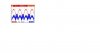
I am working with an inverter prototype which generates a waveform as indicated with red color on file attached. I need to supply the rectified output of this waveform in a low voltage level (2 Volts) to the A/D conversor input of a PIC processor. Due to the switching behaviour of the inverter system, there is a lot of noise (Spikes) involved in the low voltage signal to the A/D input.

Even with this type of feedback noisy signal the system works, but i need to remove as much as possible the noise. I was thinking about using an active fourth order Low Pass anti-aliasing filter, but it makes a phase shifting to the signal that the system can not allow.

The question is: How can i remove the noise from the Blue Signal without phase shifting the signal ?

I appreciate any suggestions.
 

Attachments

  • Waveforms.JPG
    Waveforms.JPG
    47.9 KB · Views: 186
If the frequency is stable then simply tune it with a bandpass filter. The phase will remain the same and the noise will be reduced. Make the filter a high Q and more noise will be removed but the phase and amplitude might change if the frequency drifts a little.
 
What is the frequency of the signal you are trying to remove?

Depending upon the frequency, you may be able to minimize high frequency spikes without significantly affecting the low frequency phase shift by using a slew-rate limit filter, such as a low frequency op amp with a slow slew-rate. The op amp will not be able to slew to the peak of the high frequency spikes but will readily pass the 60Hz signal. You still will likely need some low frequency roll-off on the op amp, but just make the low-pass frequency high enough to avoid significant phase-shift at 60Hz.

Typically very low power op amps, such as the **broken link removed**, have low slew rates and should be good candidates for this application. Generally the lower the power, the slower the slew rate. EDIT: An even lower slew-rate unit, for example, is the LTC1542.

Usually you want a high slew-rate op amp for better high frequency performance, but here you want just the opposite.
 
Last edited:
What is the frequency of the signal you are trying to remove?

Depending upon the frequency, you may be able to minimize high frequency spikes without significantly affecting the low frequency phase shift by using a slew-rate limit filter, such as a low frequency op amp with a slow slew-rate. The op amp will not be able to slew to the peak of the high frequency spikes but will readily pass the 60Hz signal. You still will likely need some low frequency roll-off on the op amp, but just make the low-pass frequency high enough to avoid significant phase-shift at 60Hz.

Typically very low power op amps, such as the **broken link removed**, have low slew rates and should be good candidates for this application. Generally the lower the power, the slower the slew rate. EDIT: An even lower slew-rate unit, for example, is the LTC1542.

Usually you want a high slew-rate op amp for better high frequency performance, but here you want just the opposite.
A slew rate limiter with specified slew rate limiting can be built with discrete components, but a lowpass or bandpass filter before the full wave rectifier might be sufficient.
 
A slew rate limiter with specified slew rate limiting can be built with discrete components, but a lowpass or bandpass filter before the full wave rectifier might be sufficient.


Hello Everybody !

Thank you very much for your replies. In order to clarify more the situation, i have attached 2 files with the System Scheme and the signals obtained. I need to clean the noise from the Vad waveform to the A/D conversor. On Low Voltage system, it is a common ground, i do not have any galvanic potential separation or PCB shields. I will appreciate your comments regarding how to remove the noise without phase shifting the signal of interest. In fact i do not know exactly the frequency of the noise i need to remove, but i do know the signal i need to supply to the A/D converter, which has harmonics components between 60 and 720 Hz mainly.

Regards
 

Attachments

  • 2_Files.zip
    152.5 KB · Views: 124
If you put the filter before the rectifier, why would phase shift be a problem?
 
Last edited:
If you put the filter before the rectifier, why would phase shift be a problem?

Roff. The problem with the phase shifting is that the controller needs to take instant actions within a closed loop for a given disturbance on the signal VL at the system output. A phase shifting would mean a delay in the action control from the processor. Anyway i will analyse deeper this point.
 
Delay is unavoidable in a filter.
What type of diodes are you using in your bridge?
 
At Vad, your noise is amplified relative to the signal. The only explanation I can see for that is a grounding problem.
Are you connecting your scope probe ground to circuit ground?
 
Roff. I agree with you. As we can see in the signals from the Scope, with the voltage divider (Resistors 1kOhm and 9.1 kOhm) the amplitude of the signal is lowered, but the noise amplitude remains unchanged, i do not know why. My scope probe is connected to ground as you mentioned.
 
Can you post a photo of your test setup?

Roff. Attached you will find 2 photos from the system. It is a prototype under development.
 

Attachments

  • System Picture Overview.JPG
    System Picture Overview.JPG
    430.2 KB · Views: 225
  • System Picture Detailed.JPG
    System Picture Detailed.JPG
    458.7 KB · Views: 159
Status
Not open for further replies.

Latest threads

New Articles From Microcontroller Tips

Back
Top