Electro Tech is an online community (with over 170,000 members) who enjoy talking about and building electronic circuits, projects and gadgets. To participate you need to register. Registration is free. Click here to register now.
Welcome to our site! Electro Tech is an online community (with over 170,000 members) who enjoy talking about and building electronic circuits, projects and gadgets. To participate you need to register. Registration is free. Click here to register now.
I am not an electronic expert. The Trigger wire would normally would be connected to the ECM. Since there is no ECM, does the module defaults to certain dwell time or some kind of limp-home mode ?
I found this: **broken link removed** Coil Dwell Calibration.htm
2. Mapped dwell (ECU has actual control of the dwell)-
This is when the ECU sets the dwell based on an internal map. The main variable is battery voltage as this has a major effect on the time needed to allow a coil to reach our target current level. The map has to be programmed correctly for the particular coil used. Nearly all production vehicles now use this method.
NEVER substitute the coil for another type on a mapped system. The ECU will not know you have done this and will still turn the coil on for a certain time, if your new coil charges quicker (lower inductance) then the coil or ECU will be damaged. If a slower charging coil is fitted (higher inductance) you will get a poor spark.
The ECU controls a switching device (transistor usually) to switch the coil on for the exact time it needs to reach the desired current level before turning it of for the spark. The transistor (known as ‘end stage’ or ‘driver’ also) may be mounted inside ECU, mounted external or even be built into the coils as is common.
This is the type of dwell control we will concentrate on in this article now and will detail the calibration process.
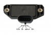
These are not ‘modules’, they are driver transistors. The LH unit (Bosch BIM 200) is two drivers in a single housing. The RH unit is a Mitsubishi J121.
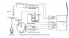
Your link doesn't work. But heres some pictures of how to wire it up. The reluctor distributor you had in your picture (8 cyl) will work driving the J121 unit, timing advance & retard is done with the vac unit on the distributor. The reluctor coil polarity needs to be correct if it isn't the spark will be poor or non existent at cranking speed.
If you are worried about Dwell, try this Bosch ADY17 module. Its designed for carby vehicles that use a Reluctor distributor (older Fords). These to need to be mounted on to a decent Heatsink. That's all the options ive got for you.
Hi debe. I greatly appreciate your help! Great discussion. Most people who decide to convert to HEI module, they use old GM 4-pin. I am thinking surely there are other better option then the version that was developed by GM in the late 70's! The link below is working.
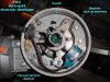
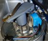
debe, one more question. There was another HEI module that GM used before they switch to distributor less ignition. This one was used with Multi-Port Fuel Inejction. It's a very nice design with module, heat sink and coil mounted on a single bracket. We had a $50 all you can carry day at our local salvage yard. I manged to grab 3 of these while I was getting other stuff.
Do you know anything about this one? Can it work like the J121 or the other you mentioned ?
What you have there is a module driven by an ECU, so according to the article on Dwell its not suitable. This only leaves 2 that I can think of, GM 4pin HEI or Bosch ADY17 (BIM024) That article on Dwell was very interesting reading. Also we don't have those GM 4 pin HEI modules here in Australia.
After reading that article on Dwell, decided to see what the waveform was like across the coil primary. Drive was a reluctor & the modules were Bosch ADY17 & a Toyota module that were design for reluctor distributors. Also the J121 unit. They all give a good spark & reasonable dwell.
I did some experiments on my bench today. The GM's MPI HEI module and the J121 module works to but only at higher RPM. I assume this is because its not seeing the very slow pulses from the reluctor. I attached one of the wire from the reluctor to the trigger and the other one to ground.
When I rotate the distributor slowly, it will not fire. If I speed it up a little with my fingers it fires. This would make it to hard to start the car!
Wondering is there a cheap sine wave to square pulse generator ?
I want to use the Ford TFI Module with points, but i have a questions, the diagram is the same as the photo? and Can it work with a coil with resistor?
debe, I believe your coil resistances are reversed. A low reading on the primary would quickly drain a battery or driver output device, while warming the coil. Without a ground reference, how does that coil generate a spark?
The TFI module has a switching transistor in it. This grounds the neg side of the coil & then opens to create a spark. The TFI module also has current sensing, so if the points are closed When the engine stops for longer than a few seconds it switches open & stays that way, untill it sees pulses again.
This site uses cookies to help personalise content, tailor your experience and to keep you logged in if you register.
By continuing to use this site, you are consenting to our use of cookies.