ZERS
New Member
Hi all,
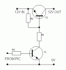
Searching through this foru,I found somme interessting things about controlling relays from a PIC.
To sum up :
1- The relay must have is own PSU instead of sharing its PSU with the PIC one.
3- A NPN transistor should be placed between the trigger and the relay.
:?: How rating this transistor ?
2- The current from the PIC is 5V/25mA. Depending on the chosen transistor, it might be necessary to place a resistor between the PIC and the base of the transistor in order to get the current down to the max of mA accepted by the NPN.
Do Am I wrong ?
I will try to make a schematic later on
Cheers