Continue to Site

Welcome to our site!

Electro Tech is an online community (with over 170,000 members) who enjoy talking about and building electronic circuits, projects and gadgets. To participate you need to register. Registration is free. Click here to register now.

  • Welcome to our site! Electro Tech is an online community (with over 170,000 members) who enjoy talking about and building electronic circuits, projects and gadgets. To participate you need to register. Registration is free. Click here to register now.

Relay opening is breaking an inductive current...is it a problem?

Status
Not open for further replies.

Flyback

Well-Known Member
Hello,
Please can you help to solve the problem of overvoltage damage to a relay which breaks inductive current in a LC filter?
I am doing a retrofit of LED reverse lights into a car. -Previously, these used incandescent bulbs in this car.
The power to the LED lights is the same as when the incandescants were used…that is, an upstream relay simply switchs off power to the LED lights, just as it did with the previously fitted incandescent bulbs.
However, the LEDs are powered by an SMPS LED driver, and as such , we need to have an LC filter at the input to the Reverse Light module.
When the relay switchs off, the inductive current in the filter inductor rings with the input capacitor and the input node to the reverse light, which is also the relay node, rings up to 120V.
The high voltage ringing at the relay node will damage the relay, do you agree? (due to sparking at its contacts as it opens)
Should we put a freewheeling diode around the filter inductor to reduce this voltage?

Please find attached,
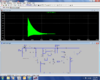
1…a picture of the ringing voltage waveform at the input node.
2…The LTspice simulation
3…The schematic.
 

Attachments

  • switch damage.asc
    7.5 KB · Views: 214
  • switch damage.pdf
    14.2 KB · Views: 180
  • Overvoltage at INPUT node.jpg
    Overvoltage at INPUT node.jpg
    73.6 KB · Views: 172
Thanks, much better......in fact, at first, I tried it with a freewheeling diode across the inductor.....(cathode to input)....but then I considered that high frequency switching noise from the Buck LED driver loads may get through the junction capacitance of the diode, so your circuit solves that problem.

So , you have solved the relay contact overvoltage sparking problem, and now I have to convince my boss that its worth adding the diode to the PCB....so can you say that the original circuit, without the diode, is likely to damage the relay?..due to contact sparking at relay opening time.
 
Hi,

As you noticed when an inductor with current through it is open circuited the voltage can jump up or down by a huge amount. In this case it is limited by the capacitor C6 of 470pf. That capacitor acts in conjunction with the inductor so that it oscillates for a while, and that keeps the voltage from jumping down to negative infinity in theory when the relay contacts open.

Since this capacitor acts to limit the voltage, it may also help to increase the capacitance, although the diode should work pretty well without that change.

There is one more caution here though, and that is during the time when the relay contacts CLOSE. When the contacts close the capacitor has to charge from zero to +12 volts and because there is little series resistance it will do so very fast, which means it will draw a lot of current. This could destroy the capacitor. Luckily there is usually some series resistance in capacitors but to make sure it doesnt hurt to add a little in series. Adding 10 ohms will keep the surge current down to 1.2 amps which is probably reasonable. Depending on the inductor current this wont change much except to protect the capacitor, and with the added diode it wont hurt at all.

The diode current rating should match the inductor current at the time the relay contacts open. That would be equal to the normal max circuit current when the relay is closed.
 
i think my boss may still say I am paranoid if I tell him we need to take steps to get rid of this relay overvoltage....will it really be damaged at all?...is the diode "really" necessary.....maybe ringing to 120v isn't too bad for the relay.?
 
Hi,

Well that is if it really only goes to 120v and the relay has contacts rated higher than that. Generally however it is always good to get rid of any possible arcing in relay contacts because that wears out the contacts. When the contacts open they dont open instantaneously, it takes a finite amount of time for them to reach a separation distance of any safe amount during which time they can arc over and that causes damage.

We can look at an equation that shows what the voltage can jump up to, but we have to know the load current. What is the normal load current?
 
Hello again,

Ok i did a little work on this and found that a rough approximation would be the first peak reaches 400 volts with about 1 amp, and this is roughly linear in I so we have a peak of 400 volts per amp. Thus 100ma would mean only 40v, 300ma three times that or 120v, and 350ma a bit higher than that. So theoretically this might be in the safe zone but it depends on the cap value so if that's different we could see higher too. The diode is also a known way to handle this situation without worrying about anything changing later because the diode will always clamp the negative peak. So instead of 120v we only have 0.7v or maybe a little more like 1v, which is much better for the relay contacts over time.

So it's up to you as long as the contacts are rated high enough but with the cheap diode the contacts will last longer.
 
Since it is an ac voltage I don't think you need to worry about it since it will only last 1 cycle.
 
Would a snubber like a 1 uF cap and a 470 Ohm resistor be practical? I placed a snubber across the sim and it looked OK, unless I am missing something.

Ron
 
Since it is an ac voltage I don't think you need to worry about it since it will only last 1 cycle.
so not worth putting the protection diode in then?
A snubber would help, but to be honest, the diode does the job fine
 
Don't think so. Also drops the base current that had me worried. Maybe smarter than you gave credit.
 
The high frequency of the ringing without the diode means that there will be arcing across the contacts as they open (the contacts will only be open a fraction before the voltage hits the first negative peak). The contact voltage rating does not much come into play here, since that rating is for the contacts fully open. This will erode the contacts and could cause eventual relay failure, either by the contacts welding together, or they not being able to make contact. The time for this possible failure to occur depends upon the frequency of relay operation and the contact current rating.

What is the relay current rating?
 
When I run your simulation I don't see near the voltage you have in the picture. - More like +/- 15 volts across the switch.
 
Here is my run.
Anyway, most of the current is going thru the little cap. By the way is it ceramic or?
And what is the inductor part number?
Seems to me the arc should only last 1 cycle. What does everyone else think?
 

Attachments

  • tail.png
    tail.png
    149.9 KB · Views: 158
Here is my run.
Anyway, most of the current is going thru the little cap. By the way is it ceramic or?
And what is the inductor part number?
Seems to me the arc should only last 1 cycle. What does everyone else think?
I also get over 100V peak in my simulation.

I can't resolve your part values on the schematic. Have you changed any of them from the original values?
 
designer legged it, but at the mo I know....
inductor = 68uh 730ma 0.073r
cap = 470p, and from my memory of the board, its in a big package for a ceramic, something like an 1812 or bigger.
...and no, I gave the original values...apart from the pnps cuzz I didnt have the cph3105 model
 
Status
Not open for further replies.

Latest threads

New Articles From Microcontroller Tips

Back
Top