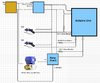
I have a small hydroponics garden that has a tank of water that is continually circulated throughout. That tank tends to empty out, so I built a simple circuit to monitor the water level, and if it gets low, trigger a valve to open and refill it. It consists of 2 float switches in the tank, and an electronically controlled ball valve (not a solenoid). I originally had the valve hooked up to 12 v on one side, and a transistor network (6 transistors in parallel) to allow the ground connection through on the other side. This transistor network was activated by an Arduino Uno. I was originally planning on using a solenoid, which is why I used a transistor network. I have everything hooked up via ethernet cable and have a waterproof coupler in the middle so that I can unhook the electronics and work on it inside if needed.
The first coupler I bought failed within a month and there was corrosion everywhere. It turns out that this somehow fried my transistor network. I'm assuming that a 12v line crossed over somewhere. Anyway, I've replaced that network with a relay. The relay works fine out of circuit, but as soon as I hook it up to a load, it just hums and doesn't fully activate. It's powered by 5v and has a 5v line in that is normally pulled low. A high signal is sent to activate the relay. This is the relay that I have:
What could I be doing wrong? I apologize for my diagram... This is just a hobby!
Thanks,
Eric
The first coupler I bought failed within a month and there was corrosion everywhere. It turns out that this somehow fried my transistor network. I'm assuming that a 12v line crossed over somewhere. Anyway, I've replaced that network with a relay. The relay works fine out of circuit, but as soon as I hook it up to a load, it just hums and doesn't fully activate. It's powered by 5v and has a 5v line in that is normally pulled low. A high signal is sent to activate the relay. This is the relay that I have:
ALMOCN 6Pcs DC 5V 1 Channel Relay Module With Optocoupler Isolation Support High or Low Level Trigger - - Amazon.com
ALMOCN 6Pcs DC 5V 1 Channel Relay Module With Optocoupler Isolation Support High or Low Level Trigger - - Amazon.com
www.amazon.com
What could I be doing wrong? I apologize for my diagram... This is just a hobby!
Thanks,
Eric