Continue to Site

Welcome to our site!

Electro Tech is an online community (with over 170,000 members) who enjoy talking about and building electronic circuits, projects and gadgets. To participate you need to register. Registration is free. Click here to register now.

  • Welcome to our site! Electro Tech is an online community (with over 170,000 members) who enjoy talking about and building electronic circuits, projects and gadgets. To participate you need to register. Registration is free. Click here to register now.

Relay driver circuit isn't driving

Status
Not open for further replies.

kybert

New Member
Hi,

Not sure why im stuck with somthing so simple as this, but i really cant work out what's wrong - <phew> i have admitted defeat! :?


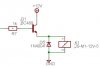
Looking at the picture attached, the transistor is driven from a PIC ( 0V or 5V o/p ).

When R1 is driven with 5V, the transistor *should* turn on, and in turn, switch on the relay.

The relay is a 12V / 400R (30mA) type, and is functional - so is the transistor.

I have checked the relay by shorting out C -> E on the transistor, it switches as expected.

The transistor has been checked in a DMM, and tested OK.

When the PIC drives the Base, the voltages in the transistor are as follows:

B: 5.1V
C: 12.32V
E: 4.5V

Not sure why the emitter is so low...


Help !
 

Attachments

  • image1_206.jpg
    image1_206.jpg
    8.9 KB · Views: 687
The base-emmitter junction will always be about 0.7V as it can be seen as a diode.

try moving the entire relay+diode setup to the top of the transistor. That is, emitter directly to ground, collector to relay and relay to +12V
 
So an emitter-follower will only work if the driving voltage (base) is the same as the collector?


I was under the impression that when a voltage is applied to the base, the transistor (simplist terms) connects the collector to the emitter?
 
well, its called an emitter follower because the emitter 'follows' the base (minus 0.7V junction voltage)...

if you were to put 12V on the base then the emitter would be at 11.3.
Now you've got 5 - 0.7 = 4.3V wich is not enough for your relay...

if you place the entire relay setup between 12V and collector like I said then the transistor will act as a ground switch.
 
Hi kybert,

Not sure why the emitter is so low...

As exo has said, changing the layout slightly will
put the transistor into a normal amplifying mode.
Then it should operate as you expect it to.

As its shown, the emitter voltage would not rise
above the base voltage because doing so would
shut the transistor, so it rises up to (nearly)
the base voltage, hence the name 'follower', in
this mode its usual job is to match a lower impedance.

Best of luck with it, John :)
 
I was using the emitter-follower as a switch to switch a higher voltage from a 5V pulse, but i got it wrong... darn.


Using the method described my Exo, will that act as an inverter as well?

( not a problem, just a simple code change )


Joe
 
kybert said:
Using the method described my Exo, will that act as an inverter as well?
No, it won't invert. 5V on the base will turn the relay on, 0V will turn it off.
 
kybert said:
I was using the emitter-follower as a switch to switch a higher voltage from a 5V pulse, but i got it wrong... darn.


Using the method described my Exo, will that act as an inverter as well?

( not a problem, just a simple code change )

As Exo says, it doesn't really 'invert', but does produce the correct switching action which your original design doesn't do. The actual transistor itself does invert, but the switching action doesn't - high will be ON, and LOW will be off.

Have a look at the 'Hardware Extras' section of my tutorials for the correct type of circuit.
 
Status
Not open for further replies.

Latest threads

Back
Top