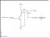
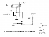
Guys, i m facing a tough problems. it is how to use relay to construct a mechanical latch when transistor is on. I would like to use DPDT relay and 2N3053 transistor.
p/s: mechanical latch means that once the relay coils is energized then the relay will permanent on until remove the the source voltage.
p/s: mechanical latch means that once the relay coils is energized then the relay will permanent on until remove the the source voltage.
")