Continue to Site

Welcome to our site!

Electro Tech is an online community (with over 170,000 members) who enjoy talking about and building electronic circuits, projects and gadgets. To participate you need to register. Registration is free. Click here to register now.

  • Welcome to our site! Electro Tech is an online community (with over 170,000 members) who enjoy talking about and building electronic circuits, projects and gadgets. To participate you need to register. Registration is free. Click here to register now.

Reg Mike's MacMux Design

Status
Not open for further replies.

Gayan Soyza

Active Member
This is regarding LED matrix based on mike(K8LH)'s MacMux design.

I have following points to discuss.

Mike(K8LH)uses a 10 pin interface to drive an 8X128 matrix design.
*RB0 – RB7 = 8 Rows
*PWM Signal
*Serial Clock Signal
*Serial Data uses the same Row lines

I see mike is cascading two shift registers at once (16bit) from a Serial Data pin. For the next 16bit using another Serial Data pin. Likewise using 8 separate Serial Data pins to feed data.

1) Why not use a single Serial Data pin (The code also will be smaller than 8 separate Serial Data pins? Is this because it will be an 11pin design?

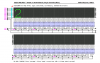
I have a new led matrix to build that is 8 X 96 design & planning to do a hardware. This is not a character display, this is a pattern display. The attachment shows how I placed RAM according to my matrix.Cascading 12 shift register at once.
 

Attachments

  • MacMux™ 8x128 Matrix.PNG
    MacMux™ 8x128 Matrix.PNG
    56.8 KB · Views: 165
  • Register Placing.PNG
    Register Placing.PNG
    9.2 KB · Views: 160
Last edited:
Hi Gayan,

Using a single serial data pin to load 12 cascaded shift registers should be fine and the code should indeed be much smaller.

That MacMux 8x128 display was simply an exercise to see how fast I could load 16 shift registers with 128 bits of data. I used unrolled loops (larger code) and I loaded 8 shift register pairs in parallel (pseudo 8-channel SPI) in 64 cycles. That works out to a bit clock rate of 4, 8, or 16 MHz when using an 8, 16, or 32 MHz clock. Another ~280 cycles are used by "data bender" code to build the special 16-byte MacMux array from which the shift registers are loaded. All in all, there's approximately ~350 cycles 'overhead' to refresh each 128-bit row on the display (~2.73 cycles per bit).

Good luck on your project. Cheerful regards, Mike, K8LH

Ah now I got what you doing..

Loading 128bits from 350 cycles is super fast. That's very clever.I just thinking to implement it but my register placing is vertical rather than yours :(

Thanks for the details.I'll show a video of my complete project once I finished it.
 
Status
Not open for further replies.

Latest threads

New Articles From Microcontroller Tips

Back
Top