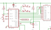
Hi guys, newbie here. I used 16F88 as my MCU and i define the port as below:
As I need B5 as my hardware UART, i am planning to switch the LCD_RS to another port which is A6 (RA6/OSC2/CLKO),
A6 buffer type is ST and i had it ground previously. However when I changed to RA6 and reconnect LCD port...it gives weird characters on the LCD.
Is it possible to do it this way? Thank you.
Code:
__16F88
 __config _CONFIG1,_BODEN_OFF&_WDT_OFF&_LVP_OFF&_MCLR_OFF&_PWRTE_ON&_INTRC_IO

; I/O pin assignments

	ifdef	__16F88

#DEFINE	PGBTN	PORTB,6	; page button   (S3)
#DEFINE	HDBTN	PORTB,7	; hold button   (S2)
#DEFINE	BLDBTN	PORTA,7	; blades button (S1)

#DEFINE	RPM_IN	PORTB,0	; rpm input

#DEFINE LCD_D7  PORTA,4	; \
#DEFINE	LCD_D6  PORTB,1	; |
#DEFINE LCD_D5  PORTB,2	; | LCD panel
#DEFINE LCD_D4  PORTB,3	; |
#DEFINE LCD_E   PORTB,4	; |
#DEFINE LCD_RS  PORTB,5	; /
As I need B5 as my hardware UART, i am planning to switch the LCD_RS to another port which is A6 (RA6/OSC2/CLKO),
A6 buffer type is ST and i had it ground previously. However when I changed to RA6 and reconnect LCD port...it gives weird characters on the LCD.
Is it possible to do it this way? Thank you.
")