Continue to Site

Welcome to our site!

Electro Tech is an online community (with over 170,000 members) who enjoy talking about and building electronic circuits, projects and gadgets. To participate you need to register. Registration is free. Click here to register now.

  • Welcome to our site! Electro Tech is an online community (with over 170,000 members) who enjoy talking about and building electronic circuits, projects and gadgets. To participate you need to register. Registration is free. Click here to register now.

Really Desperate of your help...

Status
Not open for further replies.
Hi:)

Hi everybody:)

Thank you all so much...

I'll start building the circuit now..
I'm really glad there's this site to help me..
God bless everyone:)
 
Last edited:
Jaseslin,
As promised in the reply to your PM, here is the Vdd, Vss connection diagram

Len
 

Attachments

  • vdd_vss.png
    vdd_vss.png
    2.2 KB · Views: 744
Jaseslin,
As I said in my PM, I only have a old version of Electronics Workbench and it cannot open your file.

Does anyone know how to solve this please?

The file is a layout of the circuit I posted above on May 15 - Pulse Generator1.png

Len
 
Hi Len:)

Hi Len:)

here u r..
sorry for keeping u so long :oops:
 

Attachments

  • pulse_generator_1.zip
    23.8 KB · Views: 100
Last edited:
Jaseslin,
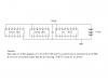
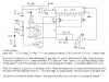
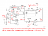
As I said in the PM, here is the circuit I am using. Your voltage measurements do not reconcile with the pin numbers shown in this diagram which is based on the bit map you posted on May 22 as pulse_generator_1.bmp.

Len
 

Attachments

  • pulse_generator_1_116.png
    pulse_generator_1_116.png
    7.8 KB · Views: 645
hi Len :)
sorry for the trouble..
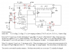
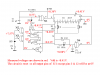
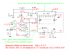
I changed the pin connection so i can arranged the connection more nicely..
the one with the red circle is changed while the one that don is maintain.

Thank you :)


[/img]
 

Attachments

  • pulse_generator_1_116_132.png
    pulse_generator_1_116_132.png
    32.9 KB · Views: 641
Last edited:
Jaseslin,
I have altered the drawing to reflect the voltages you measured (as posted on 24 May).

Len
 

Attachments

  • pulse_generator_1_168.png
    pulse_generator_1_168.png
    6.3 KB · Views: 582
hi Len :)

Here you go.

Thank you.
 

Attachments

  • pulse_generator_1_521_198.png
    pulse_generator_1_521_198.png
    27.8 KB · Views: 603
Last edited:
Hi Len :)

Here is the picture.**broken link removed**
 

Attachments

  • dscf0077.jpg
    dscf0077.jpg
    330.1 KB · Views: 572
Hi :)

I've tried on the oscilloscope but all i get is just noise..

may i know wat's is still wrong with the ckt?

thank you...

really desperate,
 
Last edited:
Jaseslin,
Your photo shows that you have made some errors in the wiring. So I have altered the circuit to show the differences in green.

Differences in pins numbers (compared to what I posted last time based on my understanding of your earlier post) won't matter but the errors will.

Note there is an error in the diagram, I should have written G1/1 not G3/1.

Len
 

Attachments

  • pulse_generator_1_186.png
    pulse_generator_1_186.png
    8 KB · Views: 255
Status
Not open for further replies.

Latest threads

New Articles From Microcontroller Tips

Back
Top