Continue to Site

Welcome to our site!

Electro Tech is an online community (with over 170,000 members) who enjoy talking about and building electronic circuits, projects and gadgets. To participate you need to register. Registration is free. Click here to register now.

  • Welcome to our site! Electro Tech is an online community (with over 170,000 members) who enjoy talking about and building electronic circuits, projects and gadgets. To participate you need to register. Registration is free. Click here to register now.

Really Desperate of your help...

Status
Not open for further replies.

Jas

New Member
Hi
i need to come out with a pulse generator..
so i went to search on the net..
n i get this circuit..
it's at
https://www.electro-tech-online.com/custompdfs/2005/05/CI-3-pulse-1.pdf
can anyone pls help me?
it's quite urgent..
i tried stimulate the circuit using workbench..
when i activate the circuit..
it doesn't come out like wat it said in the article..
i'm supposed to get a pulse when i press switch 1 but instead i get a continuous pulse..
this goes same with the other switches..
pls help me...
Thank you so much n god bless you all..


really in need of your help,


attachment included..
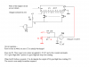
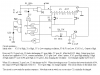
-ckt in workbench
-ckt from the net
 

Attachments

  • ci-3-pulse_810.pdf
    46.5 KB · Views: 324
Last edited:
soli..
there's another attachment tat i need to include...
the ckt in workbench...
 

Attachments

  • 123.zip
    12.5 KB · Views: 179
Last edited:
Hi Jaselin,
You should get only the correct number of pulses out if you press a switch momentary. If you press a switch continuously, you will get repeating pulses out. :lol:
 
Hi Uncle $crooge:)

Does tat mean tat if i really build the circuit out n i used the real push n release button then it'll surely work?

Coz i tried to switched the normal switch in the workbench for there's no push n release button..
i always get the continuous pulses when i on n off a switch..
i tried from switch 1 to switch 9, n the results r the same..

should i build the circuit out?

thank you:)
 
Last edited:
Jaseslin,
I received your PM and I am pleased to help if I can.

I don't have a workbench so I can't open the 123.ewb attachment.

I looked at the circuit CI-3-pulse.pdf and it looks like it will work, but it relies on the operator releasing the button before C2 discharges via R4.

Otherwise, the pulses will start again. So if, for example, you press S5 you would see continuous series of 5 pulses separated by the delay due to C2 R4 which would be about 2M x 0.22 uF = 0.4 second.

Is this what your simulator shows?

The only potential problem with the circuit that I can see is, if you built one, contact bounce from the buttons would appear in the clock pulse line if the bounces occurred while N1/3 is high.


Len
 
Bad circuit design.

If one presses the button too briefly, the circuit would not work correctly. If one presses too long, it repeats the pulses output.

Hi Jaseslin, just use a 22M resistor instead of the 2M across the 1N4148 diode to delay the reset action and you would find the circuit is now working long enough for you to check its operation.
 
HI
I think there is some major mistake in the circuit shown in the pdf file and also the explanation for circuit is contradictary
jaseslin, I dont have workbench here at my workplace so cant try simulating the circuit
So just try doing the following steps and see if it works
1) Connect pin 13 of IC (Clock enable) to GND
2) connect output of nand gate (N3) pin 10 to pin 14 of IC (clock)
I hope that after that your ckt should work
and I dont think there will be any problem by pressing the switch for long time
let me know if this work else i will try doing it myself later at my home
 
Hi Jaseslin,

There is no major mistake in the circuit but just bad design due to limited number of components use.

As ljcox has correctly pointed out, there are two main concerns that can be improved while keeping the design without adding more components like transistors and ICs.

Problem 1. Contact bounce:

By adding a 0.1uF capacitor to the pin 5&6 of N2 and changing its resistor to 2MOhms, the moment the switch is pressed would discharge this capacitor and subsequent contact bounce would have little effect to the circuit.

Problem 2. Quick recycle operation:

By changing the 2M resistor to 22M, hopefully the recycle time would be longer so that there are plenty of time for the user to release the push button.

The circuit, before modification, is from the following location and is copyrighted to the original designer.

https://www.electro-tech-online.com/custompdfs/2005/05/CI-3-pulse-3.pdf
 

Attachments

  • npulse.gif
    npulse.gif
    25.7 KB · Views: 1,033
Yeah, build the circuit with the last posted mods. Your sim is full of xxxx if it can't produce a momentary switch that is required.

Don't use the mod suggested by Instruite, he doesn't understand that the 4017's Clock Enable (not) input can be used as a low-going clock, instead of its Clock input that is positive-going. Sorry, Instruite. :lol:
 
Sorry jaseslin
My mistake, Audioguru pointed it out right
I didint saw the full datasheet and only read the first paragraph which said that it is triggered on the edge of the clock when clock enable is low
and sometimes EFY ckt do contains mistake so thought it might be one of the same cases
Any ways thanks audioguru :)
 
Jaseslin,
Here is my suggestion.

You could, in theory, alter the design to make it work without the reset button and without the timing solutions but it would need a Flip Flop to control the reset. ie. the reset would occur when you release the button that was pressed. If you want to see this option, let me know and I'll draw it for you. But this one is simpler.

Len
 

Attachments

  • pulse_generator.png
    pulse_generator.png
    5.1 KB · Views: 965
instruite said:
So just try doing the following steps and see if it works
1) Connect pin 13 of IC (Clock enable) to GND
2) connect output of nand gate (N3) pin 10 to pin 14 of IC (clock)

This is not necessary. If you look at the data sheet for the 4017, the Clock Enable can also be used as a clock input and the Ck input can be used as a control. If pulses are input to CE (with Ck High) the counter will increment on the negative edges of the clock signal.

If pulses are input to Ck (with CE Low) the counter will increment on the positive edges of the clock signal.

In fact, gate N3 is not necessary as the output of N2 could have been connected to IC1/14 (Ck) ie. use Ck as the control.

Len
 
ljcox said:
In fact, gate N3 is not necessary as the output of N2 could have been connected to IC1/14 (Ck) ie. use Ck as the control.
I agree. :lol:
 
Hi ljcox,

ljcox said:
....but it would need a Flip Flop to control the reset....In fact, gate N3 is not necessary as the output of N2 could have been connected to IC1/14 (Ck) ie. use Ck as the control.

I have now also removed N4 from the circuit. This would leave N3 and N4 not being used and free for other purposes.

Its your turn again to build the reset circuit using a Flip Flop out of N3 and N4. :lol: :lol: :lol:
 

Attachments

  • npulse1.gif
    npulse1.gif
    8.6 KB · Views: 834
Here it is. Unfortunately, an RS Flip Flop made from NAND gates has active low inputs and I needed active high. I know I could use inverters, but why add an inverter package when a NOR package makes a more elegant solution?

Also, package N could now be a Hex Schmitt Inverter package, but I did not bother to change it.

Contact bounce should not be an issue since the bounce when a switch is pressed is absorbed by the R1/C1 delay and bounce when the switch is released is of no consequence since, once the FF is set, extra set pulses are ignored.

Len
 

Attachments

  • pulse_generator_1.png
    pulse_generator_1.png
    7.5 KB · Views: 802
Excellent piece of design work. :D

Especially that of using the Q0 output to detect the release of the switch and the clever delay of reset feature. Very very cool.
 
Status
Not open for further replies.

Latest threads

Back
Top