Continue to Site

Welcome to our site!

Electro Tech is an online community (with over 170,000 members) who enjoy talking about and building electronic circuits, projects and gadgets. To participate you need to register. Registration is free. Click here to register now.

  • Welcome to our site! Electro Tech is an online community (with over 170,000 members) who enjoy talking about and building electronic circuits, projects and gadgets. To participate you need to register. Registration is free. Click here to register now.

Real simplest and most practical ESR meter circuit

Status
Not open for further replies.
Any experienced expert in creating some testing instrument here ?

What'd the simplest, cheapest and most practical ESR meter circuit be, requiring only 6 V PS (not 9 as usually) while it's reliable enough to perform a test with ~ 2% (or even just 2.5%) tolerance
 
Last edited:
The answer depends on your ESR resistance range; a CMOS '555 can do a few milliamps of square wave,
and an oscilloscope readout will show resistance at the 0.1 ohm level, but some
low-ESR capacitors are spec'ed for 0.01 ohms (ten milliohms), so a 2%
tolerance means detecting a (0.02 * 0.010amp *0.010 ohms = 2 microvolts)
very tiny step voltage. It would be best to use a four-wire probe for such a measurement.

Large-ish electrolytic capacitors (330 uF) and up that fail due to high ESR are usually
in the 1.0 ohm ++ range, and you don't need accuracy to know that they're bad.
Exactly, for service purposes you don't need any sort of accuracy - and duff caps are mostly MUCH higher than the 1 ohm whit3rd suggested.

I've tested, and replaced, thousands of electrolytics - and almost always you go 'wow' when you find a faulty one, and just can't believe it still worked to any degree. Generally you don't even pay attention to the numbers - you just run along the capacitors until one jumps out and grabs you :D

A 330uF at 1 ohm should certainly be changed, but doing so would be unlikely to cure the fault - it's more for future prevention.

A lot depends, as usual, on exactly what the OP is trying to do - if it's simply testing capacitors out of circuit, then the cheap Chinese component tester kits would be fine, as most now do ESR (but not very well in-circuit).

I used a home made (out of TV Magazine) analogue one for a number of years, then bought a Peak Electric one, which I can highly recommend (and they are made not too far from me).

 
I used a home made (out of TV Magazine) analogue one for a number of years,

I made and still use that same TV Magazine Meter .. .. . works for me ..

ESR Meter.jpg


MM
 
I made and still use that same TV Magazine Meter .. .. . works for me ..

View attachment 133812

MM

I made two, one for work and one for home, I gave them both away long ago.

Nice job on the scale - presumably the one printed in the magazine?.

I did scan the entire article, but I can't find it any more?.

Edit: If you type in 'esrmeter' in the search box on Windows it finds it for you! :banghead:

This is scanned, OCR'd, and edited from the original articles.
 

Attachments

  • esrmeter.pdf
    119.1 KB · Views: 764
Last edited:
:) I was just going to send to my PDF of the article that you sent me in 2015 !

The scale is the one in the article but I edited it with a bit of software called ' Meter Basic ', quite good.

MM
 
:) I was just going to send to my PDF of the article that you sent me in 2015 !

I just couldn't see it - and it was even where I looked :D

Did you build it from that PDF?.

The scale is the one in the article but I edited it with a bit of software called ' Meter Basic ', quite good.

MM
Nice!.
 
I'm, not sure I remember, but it's unlikely I built it from anything else.
...
Look Familiar ?

MM
That's a different circuit. Yours is using a 74HCT14 (presumably a squarewave oscillator, with LPF); Nigel's is using a bunch of opamps (presumably a "sine"wave oscillator).

Is this yours, MM?
iu
 
Yep .. you're quite right !
My memory isn't what it used to be .. .. .. .. .

Mine is based on the attached article .. .. .

MM
 

Attachments

  • Yorkie's ESR Meter.pdf
    1.3 MB · Views: 519
Yep, that's the same circuit I posted. I wonder what accuracy you can expect from it. Obviously it works well enough to detect bad caps.
 
Well, I'm only slightly less of a novice now than I was when I built it so the accuracy wouldn't mean a lot to me either way.

It seems to detect a cap with an ESR problem well enough, I successfully used it a number of times; most recently an Instek Bench Power Supply that was explosive - a pair of MOV's burnt to a crisp, a large FET with the front blown off .. .. .. .. .. .etc .. .. .. .. MOV's, Bridge, FET's and most of the caps replaced .. .. now working nicely.

In the article the author actually states that accuracy is not very important so that maybe answers your question.

MM
 
That's cool that it was handy for fixing the PSU.
Even if it doesn't meet the 2% requirement of the OP, it's so simple that I think I'll have to build one, but will swap out the 74HC14 for a LM555C.

Cheers.
 
You're very welcome .. .. ..

Nothing more than curiosity .. I'd be interested to see the LM555C circuit when you've done ?

MM
 
Sure, I'll post a piccy when I get it all sorted
 
That's a different circuit. Yours is using a 74HCT14 (presumably a squarewave oscillator, with LPF); Nigel's is using a bunch of opamps (presumably a "sine"wave oscillator).

Is this yours, MM?
iu
The article from TV Magazine suggests that using a sinewave is advantageous, I've no idea what difference it makes in practice. I'm presuming the multiple 680 ohms (to increase drive power) and 47nF above are to 'round off' the squarewave to approximate a sine?.
 
I have a design based on Luden's design which you can refer to at https://ludens.cl/Electron/esr/esr.html

Why I chose this design? It is conceptually simple, and technically sound. One might be turn off by the use of transformer, but it is needed because the of impedance transformation to ensure that the output of the Op amp is terminated correctly to maximise power transfer of the 100Khz oscillation. Of course there are other means to do that like having a parallel banks of driver with 74HC14 to drive the oscillator output in some other design.

There are a number of modifications to the original design.
1. Created a virtual ground with a stronger drive
2. Change oscillator frequency to 100Khz
3. Change the ferrite transformer to 10:1 instead of the 20:1
4. Change load impedance for measurement to 5 ohms
5. Use 12V instead of 9V
6. Use a simple peak detector instead of the voltage doubler design
7. Use a buffer for the 500uA meter

Rationale for the change
1. The drive for virtual ground needs to be stronger because it need to drive the transformer input otherwise the virtual ground may noisy when the drive is too strong
2. 100Khz is better than 50Khz
3. 10:1 transformer is widely available by extracting the ferrite transformer of a flyback DC-DC (230V to 5V). This transformer will give you approximately 10:1. However, I must state than 20:1 is a better ratio, because the reflected impedance to the Op will be 400*RL (load impedance). With 10:1 the reflected impedance is 100*RL
4. The original load impedance when test points are shorted in 10//10 = 5 ohms. But I have it changed to 10//5 = 3.33 ohms. So the original reflected impedance with 20:1 transformer = 400*5 = 2000 ohms, but the modified one will be 100*3.33 = 333 ohms. Peak AC current with 6Vpp output = 3 /333 = 9 mA p-p which is supportable by TL082 op amp.
5. The luden design uses 5V (9V via 5V regulator). This is mistake in the original design, because the TL062 use in the original design require at least 5V for each rail, meaning 10V minimum is needed for + and - rail. I have use TL082 which has slightly lower requirement, but I think 10V is still too low. In the datasheet, for +/-15V rail, the guaranteed swing is +/-12V which means there is an inherent lost of 3V on each rail. This means that at +6 and 6, the max swing allowed in +3V and -3V. So, I have to bear this in mind, when I use 12V. High voltage will be
better, but I stick to 12V because this DC-DC power is widely available.
6. A voltage doubler does not give much benefit because if the amplifier is allow a swing of +3V to -3V, doubling the voltage to 6V would have a swing exceeding 3V. A simple peak detector will ensure that the swing is less than what the earlier amplifier stage level input. There will be a voltage loss due to the forward voltage on the diode but that is about 0.3V when using a schottky diode which is tolerable.
7. A buffer amplifier is used to drive the ammeter because I cannot get a 50uA meter, and I want to use a cheap multimeter which already has a ohm range dial plate with scale I can use directly. The cheap multimeter is a 500uA type, so I need a low impedance source via a op amp buffer to provide a stronger drive. Note also that the gain-bandwidth product of TL082 is at 4Mhz, so I have to moderate the gain to ensure that Gain-BW product is not exceeded, max gain = 4000/100 = 40 max, but I use 10 which it think is already too high. Ideally, we should have a margin of 10, but I don't have a choice unless I use a better op-amp. This is quite obvious from the observed waveform after amplification with rounded edge where the high frequency harmonics are reduced. Hopefully, this does not cause too much errors. The original Luden's design also has this problem. With TL062, Gain-BW is 1Mhz, with 50Khz oscillation, max gain = 1000/50 = 20, and yet Luden's design is using a gain of 39. ???. So if you are using Luden's design, please use at least TL082 instead of TL062.

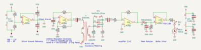
The schematic is attached for anyone who wants to build it.
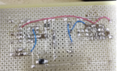
The ESR meter was build on vero board and pending arrival of the meter

Test:
1. Shorted lead - output = 2.38V
2. With 10 ohms = 0.838V
This is very close to expectation since with 10 ohms, the voltage will be at 1/3 level when it is shorted.
Meaning at 5 Ohm, will be 50% deflection, 10 ohm will be 33% deflection on the meter.
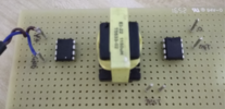
The ESR was build with SMD components so it's all on the copper side. Transformer and TL082 op amp are seen on the top side.
 

Attachments

  • ESR Analog.PNG
    ESR Analog.PNG
    21.6 KB · Views: 446
  • ESR_bottomview.PNG
    ESR_bottomview.PNG
    402 KB · Views: 352
  • ESR_topview.PNG
    ESR_topview.PNG
    234.2 KB · Views: 427
Last edited:
Status
Not open for further replies.

Latest threads

New Articles From Microcontroller Tips

Back
Top