Continue to Site

Welcome to our site!

Electro Tech is an online community (with over 170,000 members) who enjoy talking about and building electronic circuits, projects and gadgets. To participate you need to register. Registration is free. Click here to register now.

  • Welcome to our site! Electro Tech is an online community (with over 170,000 members) who enjoy talking about and building electronic circuits, projects and gadgets. To participate you need to register. Registration is free. Click here to register now.

Reading analogue value of A/D convertor with PIC 16F877A. Need Help!!

Status
Not open for further replies.

vili.chaudhary

New Member
Need help

Dear all,

My first task to light LEDs using ADC when applying DC input voltage[2V].


I will appreciate all the advise.

Many thanks.

Vili
 
Last edited:
Hi,
100 us is too much for charging the capacitor, depends on your source impedance. But usually 20 us will do for PIC16F877A. It should be shortened if you want to achieve the sampling frequency 10 kHz.
Is the code working? You should set the analog pins as input.
 
bananasiong said:
100 us is too much for charging the capacitor, depends on your source impedance. But usually 20 us will do for PIC16F877A. It should be shortened if you want to achieve the sampling frequency 10 kHz.
Is the code working? You should set the analog pins as input.

Dear bananasiong,
That's right. I did set RA0 as input in my recent code and the rest of the code is same. Thanks for pointing that out.

So do you think I should reduce my delay to say 20 us ??

If I am applying 1kHz sinwave of 2V and 50 ohm source impedance, will this code work?? I mean how practically can I realise that it's working?

Thanks again.
vili
 
Hi,
If the source impedance is only 50:eek:hm:, 20 us of acquisition time is more than enough. For the sinewave input, bear in mind that the PIC cannot handle the -ve cycle. You've got to do level shift the incoming signal.
You won't know that it is working, because the LEDs are blinking at the sampling frequency. Use potential to adjust different voltage into the pin and observe the output LED, if this works, so does the sine wave.
 
Thanks for the reply.

I have successfully implemented the above code while using the potentiometer at the input pins. Did you mean that changing the sinwave amplitude should change the LEDs blink?

I was under the impression that my PIC will do the ADC on an AC signal as well :eek: ? If not then will I have to do some rectification to have only the +ve cycle?

Please advise me on that as I have been performing all my task using ac sinwave!
Thanks.
 
Ok, for example. The ac signal is swinging from -2 V to +2V (say), but the analog input of the PIC is Vss-0.3 V minimum (if I remember correctly). So in order to get the correct samples, you have to shift up the signal, to make it say from 0 V to 4 V, so that the PIC can sample the whole range of the signal.
 
Thanks a million for your replies guys. Much appreciated.

Could you please advise me on how to shift my signal, say ,I am using -1 to +1 V? Is there any circuit to design, If so, then any guidance on that!

I will really appreciate all the help!

Thanks again.
 
Dear Nigel,

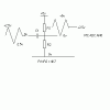
I am very thankful for your suggestion. I had a look on this forum for about 4 hours and found 1 reply by one of our members explaining the diagram [ image attahched with this reply] . I am a bit concerned about using this setting. Which values of R and C should I take??

If you see my first post, I have to perform the peak hunting of the signal as well. Do you think this technique will not affect my actual magnitude value? [ Obviously In this case I am using a -1 to 1 V sine wave, but in my project, the wave is going to be an unknown value i.e. little bit less than -1 to 1 V

Please advise!

Many thanks.
 

Attachments

  • Image1.gif
    Image1.gif
    2.8 KB · Views: 201
Nigel Goodwin said:
Component values are dependent on impedances and frequency range, as your's is 1KHz you shouldn't require a large capacitor.

Thanks again. The output from my mixer is giving me 1kHz signal all the time. It's 50 ohm impedance. Is there any formulae to calculate these values
at say -1 to 1 V? I am very much struggling in finding this :|
If you don't like the idea?, use an opamp to level shift instead.
That sounds great as well but I am again concerned about the non linearity of op amp.

I very much appreciate all these suggestions.

Many thanks.
 
Sorry for asking this again but does anyone have any idea on how to choose these values??
I have been struggling in finding these values! :(

Could someone please advise me on this. I am very much stuck and cannot make any progress in my project. :(

Many thanks.

vili
 
Last edited:
Hi,
If R1=R2=100 k:eek:hm:, so R1//R2 will be 50 k:eek:hm:. Use the capacitor that has the reactance of 50 k:eek:hm: at 1 kHz.
 
OMG..... bananasiong,

I am very grateful for your advice.

I am thinking of using two 4kohm resistors and thus 80nF capacitor with it.

Thank you again. I will keep on updating you on my progress.


Ps: One last thing, just to double check, the only thing I need to change in my code is the delay to 20 us. Am I right? But I am still confused about how I will know that my code is working properly? I know that the samples will be 10k /sec so it won't show on the LEDs blinking pattern.

Please suggest any technique where I can perform ADC on my sinewave and can confirm that YES it is working. TESTED OK!

Many thanks.
 
Last edited:
Hi,
If it works with a potential meter, for sure it works with the sinewave input if it is proper level shifted.
As for the sampling frequency, not necessary 10 kHz. It depends on the time between every samples, including the delays of every instruction cycles.
 
vili.chaudhary said:
OMG..... bananasiong,

I am very grateful for your advice.

I am thinking of using two 4kohm resistors and thus 80nF capacitor with it.

I would suggest using two 4.7K resistors, and a 0.1uF capacitor - that should work fine, your 50 ohm output impedance makes life easy.

Are you absolutely 100% sure (and triple checked) that there's nothing except 1KHz on your signal?, if there's anything higher you must low pass filter it - google for nyquist to see why.
 
Dear Nigel,

Thanks a million for bringing that point to my attention [low-pass].:)

The signal down conversion is being done by one of our project members and he is going to low pass the 1kHz signal after the down conversion from the mixer.

I am all set with my code and am using MPLAB ICD2 and wondering how to use my code as a peak detector? [ If you see my first post, I have proposed an idea as
For detecting the peak value of the signal, I will compare the last sample taken to the current one.
Take ADRESH - save to a memory location, wait 100 microseconds, take a new sample, compare to last sample, if the new sample is larger, throw out the older sample and save the newer one in its place, and so on ... until the newer sample is smaller than the older one. Thus detecting the peak = amplitude.


Could you please provide any suggestions on how to proceed with the coding bit?? A little bit of guidance could put me on the right track.

Thanks a lot again.

vili
 
Hi all,

Finally, I have done the level shifting today!!!!:)
But need help in some part of my code!

Basically I have used an op amp with a gain of 2 and a germanium diode so the output wave is halfwave rectified.

I have the theoretical approach for the code. That is by taking one sample from ADRESH move it to other memory register named PEAK, compare it to the next and if next value is less, then save that value as the amplitude. I am really stuck in how to write this in asm code? :(


I will really really appreciate any ideas !

Many thanks.
 
Last edited:
Status
Not open for further replies.

Latest threads

Back
Top