Continue to Site

Welcome to our site!

Electro Tech is an online community (with over 170,000 members) who enjoy talking about and building electronic circuits, projects and gadgets. To participate you need to register. Registration is free. Click here to register now.

  • Welcome to our site! Electro Tech is an online community (with over 170,000 members) who enjoy talking about and building electronic circuits, projects and gadgets. To participate you need to register. Registration is free. Click here to register now.

RC5 transmitter using PIC

Status
Not open for further replies.
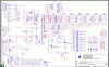
i looked into the datasheet of the pic which says to use a capcitor value between 15 to 30pF.... so i have used a 22pf capacitor....

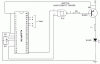
i checked all the Vdd and the Vss pins....

(1). +5V was given to pins 1, 11 and 32... (also when i checked with a multimeter there was connectivity between pins 11 and 32 )...
(2). 0V was given to pin 12 (12 and 31 had connectivity)....
 
my power supply is +5V dc... i did not add any filter cap for my power supply....

and as i said, i gave thee Vdd and Vss to all pins designated in the 16f877....
+5V to pins 1, 11 and 32.....
0V to pins 12 and 31....
 
You've got to build it right if you want it to work. 0.1uf are important in any digital circuit, and with a high current IR LED you'll also need a filter cap, say 220uf on the power pins. Add them then try it.
 
hi...

i tried adding the 0.1uF capacitors as suggesetd... but it did not work... i couldn get any results at all...

again i tested it by placing my PIC16f877 on the PIC kit (whose schematic i have included as an attachment)... and it is working fine....

Let me tell you what i did after placing the PIC in the kit....
(1). connected pin 17 and pin 21 to the inputs of a NAND schmitt trigger 74HC132....
(2). gave high inputs to the pin designated as inputs....
(3). The IR led glows and my TV operates as desired...

Why is this happening? should i make any changes to my circuit design?
 

Attachments

  • picker7.GIF
    picker7.GIF
    68 KB · Views: 309
with some finetuning i am now able to get the carrier wave (36KHz square wave) on pin 17 of the pic 16f877a....

this was generated using the PWM feature of the pic....

however i am not getting the data pulses. when i give a high on the inputs designated as l, r u and d shown in the figyre attached, i will be getting suitable data pulses (corresponding to RC5 channel +, channel - etc...) on pin 21...

what could be the mistake in the design?
 

Attachments

  • pic_circuit.GIF
    pic_circuit.GIF
    16.2 KB · Views: 197
raviram87 said:
hello people...

recently i developed this circuit (attached below).... this is a RC5 transmitter circuit... when a high signal is given at any of the inputs (designated as L. R. D and U) an appropriate function in the TV is performed (such as increasing or decreasing volume, moving channels up or down etc...)

however when i rigged up the circuit on a breadboard... the IR led shown in the figure was continuously glowing... i.e., even if no input was given...

pls help on this... wats the mistake in the design?


hello boss, plz send the code ur using for this project...
i m working on similar IR project..............
 
Status
Not open for further replies.

New Articles From Microcontroller Tips

Back
Top