Continue to Site

Welcome to our site!

Electro Tech is an online community (with over 170,000 members) who enjoy talking about and building electronic circuits, projects and gadgets. To participate you need to register. Registration is free. Click here to register now.

  • Welcome to our site! Electro Tech is an online community (with over 170,000 members) who enjoy talking about and building electronic circuits, projects and gadgets. To participate you need to register. Registration is free. Click here to register now.

RC Car computer controlled.

Status
Not open for further replies.

lloydi12345

Member
Hi guys, can you help us how to start our senior year project? Our project is about controlling an RC Car from a computer. The idea is to control a RC car using a laptop or desktop computer. So we will be using RF module to control it. We will be placing one PIC16F877a each on transmitter and receiver. Can you help us out how to start?

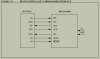
EDIT: We have planned to start everything by making an LED light which is connected to the receiver. On the other PCB there is a PIC that has a simple push button. When pressed, it will send signal to the transmitter to make the LED light. Can you suggest any schematic for receiver and transmitter part?

I would like also to go back again to C using mikroC but I think it would be hard to me if there's no guide. So I need your help on how I can go back on it again. I used to program on PIC asm.
 
Last edited:
Use simple 434mhz transmitter.
To communicate from PC to pic use rs232.
I would be able to help in assembly, not mikroC.

I would like to start lighting an LED, so far I have the schematic from the datasheet of the transceiver.. got no idea yet on the assembly code. Maybe I could do this on assembly code. Can you guide me? I don't know how to start the initializations of the PIC's functions.
 

Attachments

  • Capture.JPG
    Capture.JPG
    27 KB · Views: 238
Last edited:
Maybe this will help a bit, it's for the 16f887, but I assume the 877a will be just about the same

Code:
;*** SPI ***
; MAKE SDI TRIS BIT AN INPUT!	
;{
;SSPSTAT: SYNCHRONOUS SERIAL PORT STATUS REGISTER	
	bsf		STATUS,RP0					; Bank 1

	bsf		SSPSTAT,SMP					; 1 = Input data sampled at end of data output time ( Master Mode)
	bsf		SSPSTAT,CKE					; 1 = Transmit occurs on transition from active to Idle clock state	
	bcf		SSPSTAT,BF					; 1 = Receive complete, SSPBUF is full

	bcf		STATUS,RP0					; Bank 0
	
;SSPCON: SYNCHRONOUS SERIAL PORT CONTROL REGISTER
	movlw	b'00000010' 				; = SPI Master mode, clock = OSC/64
	movwf	SSPCON

	bcf		SSPCON,WCOL					; 1 = An attempt to write the SSPBUF register failed because the SSP module is busy 									; (must be cleared in software)
	bcf		SSPCON,SSPOV				; 1 = A new byte is received while the SSPBUF register is still holding the previous data

	bsf		SSPCON,CKP					; 1 = Transmit happens on falling edge, receive on rising edge. Idle state for clock is a high level.
	bsf		SSPCON,SSPEN				; 1 = Enables serial port and configures SCK, SDO and SDI as serial port pins	

;***

	movlw	.99		;random
	movwf	SSPBUF

	bsf 	STATUS, RP0 ;				; Bank 1
	btfss 	SSPSTAT, BF 				; Has data been received (transmit complete)?
	goto 	$-1							; No
	bcf 	STATUS, RP0 				; Specify Bank0


;}

Thanks birdman. Is synchronous better than asynchronous?
 
Hi Birdman and lloyd.

@lloyd: The transceiver you have posted in the above picture is Microchip's Zigbee Transceiver which requires the Zigbee Stack to be implemented in the processor(over kill if you are using the 19F877A). You can use MIWI(MCs propriety low data rate replacement for the zigbee protocol but still requires a stack as well and may run on your processor even!) If you want simple wireless communication than i would recommend what birdman suggested with a simple RF 434Mhz Tx/Rx. They are cheap and dont require any special peripherals(I2C,SPI etc) to to use it. Just send the data bit by bit. If you have decided on using the MRF24J40MB Module, than here is where you get all the information.

**broken link removed**

Whew! really thanks for telling me that there are 434 Mhz RF modules! I googled them and they're far a lot better than the RF Module I've posted. You saved us alot of budget for the project. If I'm not taking alot of your time, can you help me how to start from scratch? like doing remote lighting LEDs first. Can you suggest any reading materials for me? Really really thank you again.
 
Status
Not open for further replies.

Latest threads

New Articles From Microcontroller Tips

Back
Top