hello.
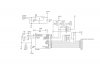
i made a simple circuit attached.
to count interrupt at RB0, the software start and make u edit the number of pulses and then start the interrupt , when the number of pulses reach what u want , it stops
the pic is attached to push-switch and lcd via sockets.
the circuit works very well on easypic 3 where rb0 is attached to pulldown resistor of 10k
when i made the circuit outside the devboard
i get solid blocks all over the lcd, untill i connect RB0 to +v, then it works !!, if i try to pull it down as in easypic3 , it wont work, attach a resistor to +v , dont work
i tried everything
setting pin as input , as output, pulling up/down floating pins , nothing works except connectin RB0 to +5V ,
but then how can it count if its always connected to +5
i will appreciate any help please
thanks
")
")

