Continue to Site

Welcome to our site!

Electro Tech is an online community (with over 170,000 members) who enjoy talking about and building electronic circuits, projects and gadgets. To participate you need to register. Registration is free. Click here to register now.

  • Welcome to our site! Electro Tech is an online community (with over 170,000 members) who enjoy talking about and building electronic circuits, projects and gadgets. To participate you need to register. Registration is free. Click here to register now.

Range of ADC, can it be changed?

Status
Not open for further replies.

LijoeThomas

New Member
I am kinda new to handling ADC's, so bare with me all ye enlightened ones.

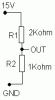
I need to digitise an input which varies from 0v to 1.5v using a ADC0804.
The range of this IC, i believe is 0-5v. Can we modify the range in which it works, say 0-1.5v so that i can have a better resolution.

Thanks.......
 
Actually i need as high a resolution as I can get by reducing the range and at the same time try to use a 8bit adc such as the adc0804.
My source gives an ouput from 0-1.5V

for example: if the range is 0-1.5V the resolution is going to be approx 6mV whereas as if the range is 0-5V then the resolution is 20mV.

So what i need to know is that if the Vref/2 can be set to .75V so that the range is only from 0 to 1.5V. I didnt not fully understand this from the datasheet.

If someone could help with this, would be grateful.
 
LijoeThomas said:
Actually i need as high a resolution as I can get by reducing the range and at the same time try to use a 8bit adc such as the adc0804.
My source gives an ouput from 0-1.5V

for example: if the range is 0-1.5V the resolution is going to be approx 6mV whereas as if the range is 0-5V then the resolution is 20mV.

So what i need to know is that if the Vref/2 can be set to .75V so that the range is only from 0 to 1.5V. I didnt not fully understand this from the datasheet.

If someone could help with this, would be grateful.
An amplifier will work better. If you amplify a 0 to 1.5 volt signal by 3.33, you will now have a 0 to 5 volt signal. Each 6mV increment of your input signal is 20mV at the output of the amplifier.
The problem with reducing the A/D range is that it may have errors that don't scale. As an example, let's say it has a 6mV error at the point where the MSB changes. At 5V full scale, that's only a 1/3 LSB error. If you reduce the reference to 1.5V, the error is now a full LSB.
This type of error may or may not exist in your A/D, but in general, it is good practice to run the A/D at it's maximum full-scale range for best performance.
 
Hey Ron, Thanks for the idea. My input was initially 0-15V, which I had used an opamp to divide by 10, which gave me 0-1.5V.

I'm going to replace that with a divide by 3 [so the o/p is 0-5V] so that I still get the same resolution. Thanks for the solution.

I'm really grateful.....
 
LijoeThomas said:
Hey Ron, Thanks for the idea. My input was initially 0-15V, which I had used an opamp to divide by 10, which gave me 0-1.5V.

I'm going to replace that with a divide by 3 [so the o/p is 0-5V] so that I still get the same resolution. Thanks for the solution.

I'm really grateful.....
If your A/D has high input impedance (many do), then you don't need an op amp. You can just use the resistive divider.
 
Can you draw me a sample resistive divider network? I'm not very sure if what I know is right.
 
ITs just two resistors wired in series, where the ends are connected to your 0 and 15V and the center between the two is the output...

Uo=Ui(R2/R1+R2)

For you R1 could be 2K and R2 1K so you get 1/3rd of the voltage on the output.
 
Heres the pic...
 

Attachments

  • resistor_divider.gif
    resistor_divider.gif
    882 bytes · Views: 347
The ratio of the two resistors needs to be 2:1, as drrogla pointed out. The actual values depend on how much loading your A/D can tolerate, and the input resistance of your A/D. It may also depend on the conversion rate.
If you can tell us those three parameters, we can be more helpful.
 
Status
Not open for further replies.

Latest threads

New Articles From Microcontroller Tips

Back
Top