Continue to Site

Welcome to our site!

Electro Tech is an online community (with over 170,000 members) who enjoy talking about and building electronic circuits, projects and gadgets. To participate you need to register. Registration is free. Click here to register now.

  • Welcome to our site! Electro Tech is an online community (with over 170,000 members) who enjoy talking about and building electronic circuits, projects and gadgets. To participate you need to register. Registration is free. Click here to register now.

Randall RH100 repairing distorting amplifier

Status
Not open for further replies.

Leandro Dias

New Member
Hello,

This is my first post.

I'm trying to fix a Randall RH100 that is having an ugly and thin distortion signal even in the clean amp. It used to be a very good clean, now it is like a bad radio with too much volume in it.

So far the symptoms:

- It has sound but thin and distorted, even in clean.
- volume is lower than usual.

Procedure so far:

1. I tested to check if it was the preamp or the power. The pre amp is fine, sending a good clean sound through the "send out" and through the headphone (also before the amp).
2. I tested the speaker and it is also fine.
3. I tested the guitar and it is also fine.

I couldnt find the schematic for the GA-75-B (written on pcb), but i found the one in RG-75B and they are very similar. Below:

randall-rg75b-power-amp-sketch-gif.55060


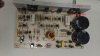
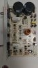
The difference from mine is that the Q15 is a toshiba 2SC3281 not a 2SC5198 and the Q14 is a 2SA1553 not a 2SA1941. This might've been changed when it went to repair two years ago. But, apparently, as shown below, there is no visible fault (see attached picture).

My suspect is the q15, due to small burning nearby. But might've been from the first time it went to repair, 2 years ago. Anywhere to start? It has too many transistors to change.

Have a good day

Leandro
 

Attachments

  • Ga-75B pcb.jpg
    Ga-75B pcb.jpg
    455.9 KB · Views: 721
Hi Leandro Dias,

Welcome to ETO (interesting avatar).

Shame about your amplifier failing, for the second time it seems.

From what I have read on the internet, the Randall RH100 has a tendency to overheat; at least one person has used a computer fan to cure the problem.

The RH100 amplifier is a pretty conventional design and finding the fault should not be too difficult.

The symptoms that you describe do suggest that one half of the output stage has blown as you mention.

The circuitry around Q4 and Q5 looks complicated but it is fairly straight forward and has two simple functions:
(1) To mute the amplifier at turn on to prevent thumps and clicks in the speakers (C5 & R5).
(2) To shut down the amplifier if the amplifier overheats to protect it (RT1).
A fault in this area could also give the symptoms that you describe.

Q10 and Q11 protect the output stage from over current. A fault in this area could also cause the symptoms you describe.

The schematic for the Randall RH100-G2, which gives a bit more information but otherwise is similar to the schematic you have posted, is attached below.

spec

(PS: I see you are from Brazil; care to put that next to 'Location' on your user page so that it shows in the window at the left of your posts)
 

Attachments

  • Randall_RH100-G2_guitar_amp_service_manual.pdf
    56.8 KB · Views: 556
Last edited:
One way to locate and fix the fault/faults on your RH100 will be to use a digital multimeter to make various voltage measurements and possibly current measurements, which I can define.

It will then be necessary to desolder/unscrew components and replace them with new, possibly more robust components.

It will also be best to correct any inherent problems with the design: off the top of my head the quiescent current control in the output stage looks as though it could cause excess dissipation in the output transistors and the heat sinking appears to be rather skimpy.

All these problems can be fixed, but it depends on the equipment you have and your skills/experience in electronics. So can you advise if you have:
(1) Digital multimeter
(2) Miniature soldering iron and solder
(3) Miniature wire cutters
(4) Miniature pliers
(5) Screw drivers

Also can you advise if you would be able/prepared too carry out the tasks outlined above.

Apologies for asking so many questions.:)

spec
 
Last edited:
Hi spec,
I've been wondering for some time how you manage to work out which country a memeber of the forum comes from when they do not give any information in their profile. Could you explain ?

Les.
 
Hy Les,

You make me sound so smart when I always think everybody else is smart with the things they do on ETO.:)

If you click on a member's name, then click on 'Profile Page' and then click on 'Information', you can see all the data that a member has entered about himself. Location only displays in the window on the left of posts if the member has filled in 'Location' on their profile page.

If they do not enter their location on their profile, I may PM them and ask or ask in a post under their first thread. I don't know of any other way to find a member's location.

As you may have guessed lack of 'Location' is a problem for me, because it makes it difficult to target answers to the OP: component access, mains supply, English comprehension, general outlook.

It would be a good move to make location (to country level at a minimum) mandatory on ETO in my opinion, unless the member made a specific case for not giving their location. In countries with counties/states/provinces it would be advantageous to give these too. To me it is always interesting to know a person's location and is one of the fascinating aspects of ETO.

spec
 
Last edited:
Hi Spec,

Thanks for the deep and quick answer.

I can do much of the tests. I'm in half of my electronics graduation (technical) so i'm not completely noob, but not experienced. With much patience, comparison and time, i usually fix simple stuff such guitar pedals and simple electronics (which appears to be this case).

I have two digital multimeters (one capable of capacitance measures) and all equipments you mentioned.

One problem that i will fix, despite it is/was working is that the output transistors are not equivalent nor complimentary to each other. The 2SC3281 is complimentary to the 2SA1302, not the 2SA1553. Would this cause some problem soundwise? The datasheet only suggests that the ones installed now can handle more power.

And commenting about the design, there is another huge dissipation panel that is not shown in the picture, going below the circuit, attached to the cabinet. I didnt need to take it out to change components. It is an extension of the one seen on picture.

Thanks again for the answer Spec.

****

About my avatar it is a funny book of some conspiracy theorist of the 60s. I found it hilarious.
 
Hi Spec,

Thanks for the deep and quick answer.

No probs LD. Afraid I am a bit of an amplifier anorak and also have a friend who has a business repairing musical gear, especially amps.:)

I can do much of the tests. I'm in half of my electronics graduation (technical) so i'm not completely noob, but not experienced. With much patience, comparison and time, i usually fix simple stuff such guitar pedals and simple electronics (which appears to be this case).
Excellent. So long as you have a logical and thorough approach, between us we should sort your amp and I'm sure other members will help too.

I have two digital multimeters (one capable of capacitance measures) and all equipments you mentioned.
Ah that is good news.:cool: You don't happen to have access to an oscilloscope too?

One problem that i will fix, despite it is/was working is that the output transistors are not equivalent nor complimentary to each other. The 2SC3281 is complimentary to the 2SA1302, not the 2SA1553. Would this cause some problem soundwise? The datasheet only suggests that the ones installed now can handle more power.
Do not worry about changing the output transistor types. I will sort all that. By the way, there is no such thing as complimentary transistors at the semiconductor level.

And commenting about the design, there is another huge dissipation panel that is not shown in the picture, going below the circuit, attached to the cabinet. I didnt need to take it out to change components. It is an extension of the one seen on picture.
That is also good news and dispels my concern about a skimpy heatsink.:)

About my avatar it is a funny book of some conspiracy theorist of the 60s. I found it hilarious.
Oh! I see. Sounds interesting.:p

spec
 
Last edited:
Hy again LD,

Having sorted the preliminarys, this is what I propose: I will post a list of numbered questions and tests for you to answer/make and if you agree can you respond exactly and specifically to each numbered question/test?

spec
 
Hi spec,
Thanks for the answer. I did not know you could get more information than shown when you click on the members name. Like You it annoys me when no location is give particularly when the question is like "where can I obtain xxx" or similar.

Hi LD,
What did you mean by "clean amp" in your first post ? The first tests I would do are checking that the + and - supply rails are at similar voltages and the the DC level on the output is close to zero volts.

Les
 
Hy Les,

No probs:) Yes it can be very frustrating trying to answer some posts. In this case though, the OP has been pretty informative.:cool:

'Clean' in music amp terms means a channel, normally in the preamp, with no distortion. So you might feed a clean voice channel and a dirty (gross distortion) electric guitar channel into a singe power amp. Musicians have a whole range of terms which electronics people need to decode.:D

spec
 
Last edited:
Hi Again folks.

Thanks for all the tips Specs. Very helpful.

Since the parts are kinda cheap, I bought most of the transistors (except the two output ones q15 e q14) and so far i've replaced the ones showing signs of excessive heat on the board (Q9, q10 and q4).

Initially the sound was beautiful again, but after 15-20 minutes of use, it went back to the same problem. So i probably hit the symptons, not what causes it.

I don't have an osciloscope to test the sign. Planning in buying a two channel one.

Q8 tends to heat too much, despite having no signs of damage or overheat, it will be my next target.
 
Hy Leandro,

I take it that you do not want to go through a fault finding procedure as I suggested in post #9

By the way, Q8 should never get hot.

spec
 
In this design it is clear that they expect them to get hot. It is the only TO92 transistor that literally goes inside the heatsink.

Specs, Sorry i didnt noticed that post #9!

I will sure do that. No problems. thanks for the patience.
 

Attachments

  • randall amop.jpg
    randall amop.jpg
    367.3 KB · Views: 765
In this design it is clear that they expect them to get hot. It is the only TO92 transistor that literally goes inside the heatsink.
:p I am not laughing at you Leandro: I'm laughing at what you say because it is so ironic.

Q8 and D5 maintain the quiescent current (normally around 20mA) in the two output transistors. They do this by tracking the two VBEs (Voltage Base Emitter) of Q12 and Q13, each of which drop by 2mV per degree C increase in junction temperature. The reason why Q8 is in thermal connected with the heatsink is so that Q8 heats up as the heatsink heats up, so its voltage also drops (approximately) in sympathy with the drop of the VBEs of Q12 and Q13. Q8 self dissipation should only ever be a few milli watts. Note that the heatsink is only heated by the output transistors Q14 and Q15, but as Q12 and Q13 drive Q14 and Q15, Q12 and Q13 get hot in sympathy with Q14 and Q15 (hope you can follow all that).

Specs, Sorry i didn't noticed that post #9! I will sure do that. No problems. thanks for the patience.
No probs. I will put together some tests and if you can carry them out hopefully, between us, we can get to the root problem with your amplifier.

With power amps one danger is that they can oscillate which will normally destroy some of the semiconductors.

What load are you putting on the amplifier: are you using a 4 Ohm loudspeaker?

spec
 
Last edited:
I think i'm following. Some technical terms in english are different than in portuguese, but i think i'm following.

- The speaker i am using is 8 ohm with this Randall, triple checked.
 
(1) The first thing to do is to inspect the board for any broken tracks, dry joints, or broken components. Any joints that look suspect reflow with new solder.

(2) The next thing to do is to check the frequency stabilizing components (probably easier to simply replace them all):
(2.1) C8
(2.2) C9
(2.3) C7
(2.4) C12/R27

(3) Make sure that the cases of the output transistors are not shorting to the heatsink.

(4) There should be two big capacitors connected from the plus and minus supply lines near to the amplifier to 0V. Make sure these are connected and are not leaking or bulging. Check the values if you can.

spec
 
Last edited:
With no signal into the amp:

Connect the negative terminal of your multimeter to OV and make the following voltage measurements:

(5) Positive supply voltage on the emitter terminal of Q14

(6) Negative supply voltage on the emitter terminal of Q15

(7) Voltage at the junction of R24/R25

spec
 
Hi Specs, I`ve did some voltage tests in some transistor and the Q8 was odd. So i changed and the amp got back to normal.

Thanks a lot for the patience. I am still crude in this, but this forum is fantastic.
 
Status
Not open for further replies.

Latest threads

New Articles From Microcontroller Tips

Back
Top