Continue to Site

Welcome to our site!

Electro Tech is an online community (with over 170,000 members) who enjoy talking about and building electronic circuits, projects and gadgets. To participate you need to register. Registration is free. Click here to register now.

  • Welcome to our site! Electro Tech is an online community (with over 170,000 members) who enjoy talking about and building electronic circuits, projects and gadgets. To participate you need to register. Registration is free. Click here to register now.

Ramping up DC power

Status
Not open for further replies.

DSGarcia

New Member
I am looking to purchase a Windows CE based computer for a project. I will power the computer from an external 24 VDC power supply. The system has the following requirement: "At input voltages between 14 and 24 VDC, voltage must be ramped up at a maximum rate of 1V/mS."

Because it is possible to plug in the connector with the power on, I cannot count on the power supply to ramp up the voltage. Is there something simple I can put in the power line to absorb some of the voltage when the unit is first plugged in--a choke or something?

The minimum power requirement of the system is 500mA at 24 VDC. The power supply is capable of producing almost 4 amps at 24 VDC and will be used for powering multiple pieces of equipment so whatever I do, it can't affect the other equipment on the power supply.

Thanks,
Dale
 
A choke would give a surge at switch-off, might not be a good idea.

At the currents you mention, i would suggest a power transistor (or
FET) in line, just to give a twenty odd milli second rise time to
full supply.
With an R-C on its base.

Suggest using a C/O switch, wired to short the cap at switch-off,
so that switching off the unit,
then quickly switching it back on,
would not stop it from going through ramping up.
 
John1,
Could you provide a circuit description and component values please? I am a software type with some electronics skills but not enough to design this sort of circuit you suggest. I would like to keep the circuit as simple as possible to solder in-line if possible. I was rather hoping to avoid using a circuit board, but will add one if I have to. This will be in a custom stainless steel enclosure and I did not have provisions for mounting boards.
Thanks,
Dale
 
Hi,

Such a circuit would be very simple.
You would have to choose the component values to suit yourself.
The transistor, or FET has simple requirements,
adequate voltage operating, and adequate current rating,
there are many that could suit.

FETs are a higher impedance device, and may be awkward to use or
to set up. For a novice i would suggest a power transistor instead.
But that is up to you, or whoever you get to construct the unit.

R2 is a dummy load, a medium to small resistor just for stability.
Maybe one or two thousand ohms. One or two watts.

R1 should be chosen as a value which will drive the transistor(or FET)
a little way into saturation. (without the cap connected of course)

The Capacitor would determine the rise time, which would not be linear
but would not matter for this purpose, and would be chosen to give a
suitable interval of rise time.
Making a long interval would make the transistor heat up, so during
trying out values bear in mind that its intended for short intervals,
long intervals may make the transistor overheat.

I imagine values of less than 10 MFD would probably be in the right area.
I have not made this, although i have made other similar units.

The function of the relay is to make sure that the cap is discharged
if the unit is turned off, then on again by accident, this will make
the unit ramp up again, as required. Its contacts are to be normally
closed, that is connected, when the relay is at rest.

Before attempting any construction, please wait to see if any others
have any comments, others may have made similar units, and might be
able to suggest or recommend likely components or values.

If i have drawn it incorrectly, i'm sure someone will soon say so.

Regards, John :)
 

Attachments

  • Ramp-up.jpg
    Ramp-up.jpg
    33.1 KB · Views: 195
John,
I think I can find a transistor that would meet the voltage and current requirements and a datasheet could let me know how to drive it. But, how would I determine the value for the capacitor? I have nothing to measure time if it were by trial and error.

Would a 2K resistor across the cap work instead of the resistor for the power-off function or would it mess up the timing of the cap?
Thanks,
Dale
 
Hi Dale,

Interesting.
What effects do you think might happen if you do that ?

(I will be reading your answer carefully,
please include reasoning)

Cheers, John :)
 
john1 said:
Hi Dale,

Interesting.
What effects do you think might happen if you do that ?

(I will be reading your answer carefully, please include reasoning)

Cheers, John :)

Oops, I did not realize that I would be taking a test on this subject. (I think you may use the term 'exam' in the UK.) I presume you are referring to my comment about a 2K resistor across the capacitor. First of all realize that I do not really know what I am doing and this is why I was asking for help.

I simply figured that your circuit employed a relay to drain off the capacitor when the power were turned off. My thought was to use a resistor across the capacitor instead of the relay to bleed off the capacitor when the power was cut off. While in operation, it would only draw about a quarter watt. My question though is whether this would work or would upset the timing of the circuit on power up. My second thought was that a relay is an electro-mechanical device and has some inertia to overcome before opening the circuit. I was wondering if, even for the smallest moment, a large current would be drawn through the resistor in your schematic through the closed contacts of the relay until it soon opens or if the relay fails (of course, it would be in the closed position).

Again, I really don't know what I am talking about, but more of a wondering based on my limited knowledge.
Thanks,
Dale
 
Hi Dale,

Thank you for your excellent reply.
I think i now understand what you were concerned about,
and what you thought might address your concerns.
Not really a test, but a way to gauge what was bothering you.

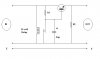
I think you were concerned about the contacts shorting out the cap.
You are correct to check that out.
Shorting out charged up electrolytic capacitors is not a good idea,
unless they are quite small values, and the charge voltage is low.
In this case, below ten micro-farhads, and twenty four volts will do
no harm. After testing the time interval the cap will probably turn
out to be less than five micro-farhads. That is just a guess, it will
depend on the R1 needed to push the transistor into saturation.

There is no resistor in that discharge loop because that is intended
to discharge the capacitor fairly quickly, so that if the supply is
plugged in live by someone wiggling the plug, or gets switched off
then back on quickly, then it will still do the ramp-up that you want.

A relay is a mechanical device, but the delay caused by its inertia
is very small, and is at the start of a small deliberately induced
rise-time, i don't think it is a concern. The rise-timing would not
start until the relay has operated, and opened its contacts, allowing
the cap to charge. Its job is not really to drain off the capacitor,
it is to ground it out quick.

Significantly, it is the absence of a supply feed that closes the
contacts, which can be done quite simply using a relay, but could be
complicated to design using electronics.

And you are quite correct, R1 will draw more current with the contacts
closed, i can only guess at a likely value for R1 for i don't know
the transistor (or FET) that you may be using, it could be around 300
ohms to push the transistor into saturation. (just a guess)
Which means that it would take around 80 milliamperes initially.
Once the relay operates, and the cap has settled, the base current
comes through the load anyway. Actually 300 ohms sounds a bit low,
you will have to check your data sheet.

The transistor is not used as an amplifier, it is used like a switch.
The value of R1 has to put the transistor into maximum conductivity.
But it is used a bit like an amplifier briefly, for the rise-time.
During this time the transistor has to handle significant wattages,
fortunately this time is brief, and the transistor should not get hot.

You quite obviously have a better grasp of what is involved than you
say. Which is why you have picked up on the apparent problem of the
contacts shorting an electrolytic. With these low voltages, and low
capacitance values, it should be Ok.

If there are others looking in, perhaps they would care to guess at
a capacitance which would give about twenty milli-seconds rise-time
for that transistor .... and it would only be a guess without the
number of the transistor. My guess is about five micro-farhads.

I did not mean to go into so much detail on my reply, but i am very
impressed by your grammar. Which appears almost faultless.
And i am impressed by your spelling, which is at least as good.
And your correct syntax, you were wondering, not wandering.
Only one slip, which shows you weren't using a checker system.

Regards, John :)
 
Last edited:
Hi Dale,

I forgot to mention,
that introducing a resistor(Rx) across the capacitor
would make R1 and Rx form a voltage divider,
which would probably prevent the transistor from reaching full
conduction.

This is bad for the transistor as the heat generated within it
is a factor of the current multiplied by its voltage drop.

Whilst either is very low, the subsequent dissipation is also low,
thats 'Amps-times-Volts',
but if neither is very low, then the 'Amps x Volts', (dissipation)
can get quite high.
Briefly: Max current is ok with very low voltage,
and its max voltage is ok with very low current,
but in-between you have to be carefull.

I hope this is not confusing, some people find these things difficult
to picture.

And i am surprised at the lack of any other response to this thread.
Are you sure that this requirement for a rise-time is not just the
manufacturers being a bit picky ... ?
Is it really necessary ?
See what others say before getting involved in making a 'Special
switch'
for this unit.

Regards, John :)
 
Last edited:
John,
Thanks for the reply. I do have some time before I need a final solution to this problem. I will consider your comments carefully and will probably need some time to ruminate on this before responding again. I have not yet purchased a unit (cost is about US$3K) but I will hit up their tech support when I do. I really just needed an understanding (and preliminary design) for when it is time to move on this project and to know what I was doing.

Regarding the voltage rise time is this note: "Voltages outside this specification will void the warranty." I can only presume it has something to do with the extended temperature TFT display but whatever the reason, I do not want to void the warranty.
Thanks,
Dale

PS, okay, okay... it should have been "power was" not "power were". I'll try to be more careful in the future now that I know I am being graded on spelling and grammer. LOL. Please allow me to sometimes use the US spelling for words such as colour, etc. I try to use correct spelling and grammer because my name is on the post. Thanks for the comments. Cheers!
 
Could anyone help me determine the values for the resistor and capacitor for the circuit suggested by John1 (and a part number for the transistor)?
Thanks,
Dale
 
hi dale, john

The circuit you have drawn looks fine, the only minor addition I would suggest
is a diode [1N4001 type] across the base/collector junction of the transistor.

Cathode to collector, anode to base.

Consider the instant the external input is switched OFF, that is the relay is energised.

Depending upon the release speed of the relay and the closure of the relay contacts
and the fact that the Cap is charged. You could momentarily have a situation where
the base/collector junction voltages are reversed . The diode would protect the transistor
and also help dump the charge on the Cap via the relay coil.

A final point would be the sequence in which the ext supply [bty] and the ramper cct and computer
are switched ON/OFF. It may require an extra diode across the emitter/collector junction.
[cathode to collector, anode to emitter], this is to prevent the transistor being damaged
due voltage reversal.

Regards
EricG
 
Last edited:
hi,
Taking a closer look at the circuit, suggests that the relay, with D1 diode
in circuit, is redundant. Just replace it with a suitable resistor.
Provided the user avoids rapid ON/OFF switching of the system.

Again it depends upon the system ON/OFF switching sequence.??

Regards
EricG
 
Status
Not open for further replies.

Latest threads

Back
Top