NewcastleSAR
New Member
Hi Folks.
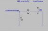
Following on from my discussion on the lighthouse circuit using either a PIC or 555 Timer, one other query I have is the ability to 'ramp' on and off the LED or Bulb.
What I means by 'ramping' is, rather than the LEd or Bulb being switched straight on or off, is it possible to switch it on gradually until it reaches its peak then gradually tail off. This would help in the lighthouse circuit to give a 'softer' flash as if the light beam was being rotated in the lantern.
Still working on the pros and cons of using either a PIC or 555 Timer.
Regards
Declan
") ... I'm in the same boat and often use pull-down (or up) resistors, probably many times when they're superfluous
... I'm in the same boat and often use pull-down (or up) resistors, probably many times when they're superfluous