jamesinnewcastle
New Member
Hi
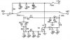
I'm looking at a CB transmitter and it states that it can deliver 4W into a 50ohm load while running from a 13.5V supply.
It is a one transistor amplifier and there are no internally generated voltage sources, so the 13.5V is all there is.
If you do the maths it appears that you need a 39.9V peak to peak sinewave across the 50ohm load to cause it to dissipate 4W. Where does that voltage come from??
I'm guessing that there is a resonant circuit but does anyone know the correct answer? I've seen other amps promising up to 200W, surely the Q needed there would be very difficult to achieve? Or is my maths just completely wrong?
Many Thanks
James