Turbo Boss
New Member
I am using a NPN transistor 2N3904 to triguer a small relay
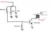
This is what I have: Emiter is conected to ground, Collector is the negative output that will triguer the relay and what I need to find is a value of R that I can use on the Base in order that it will work "FROM" +3V to +12V
At the present time I am using a R of 1K and its work perfectly with +12V but when the voltage decay to +3V it does not work.
I know I have to lower the R but my concern is if I lower it to much in order to work with 3V maybe when ir receive 12V its going to blow the transistor.
What is your advise? What R value you recomend me?
THX,
Malibu
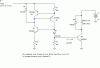
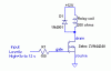
 Please check it again.
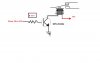