Continue to Site

Welcome to our site!

Electro Tech is an online community (with over 170,000 members) who enjoy talking about and building electronic circuits, projects and gadgets. To participate you need to register. Registration is free. Click here to register now.

  • Welcome to our site! Electro Tech is an online community (with over 170,000 members) who enjoy talking about and building electronic circuits, projects and gadgets. To participate you need to register. Registration is free. Click here to register now.

R-C switch debouncing

Status
Not open for further replies.

carbonzit

Active Member
First of all, I'd like to thank Eric Gibbs for posting links to two excellent documents dealing with this topic:

  • A Guide to Debouncing
  • Pulse Generation and Signal Conditioning Circuits (sorry, can't find the link just now; will update later)
Here's a R-C switch debouncer from the 2nd doc above. I'm sure it can be made to work well.

**broken link removed**

But here's my problem: since this uses an inverter, it generates a negative-going pulse (from a negative-going switch closure). That's find and dandy, if you want a negative pulse and if you have a normally-closed switch. But I need the opposite: a positive-going pulse from a normally-open switch.

I don't think this will work correctly if I just replace the Schmitt inverter with a Schmitt buffer, will it?

Earlier in that same document, they show this:

**broken link removed**

Couldn't I use the top version of this (with a buffer instead of inverter) to condition my switch pulse? They don't recommend this specifically for switch debouncing; but will it work?

I think I'll experiment with these to see what I can come up with. Unfortunately, I have no 'scope, so I'm pretty much flying blind here.
 
You can also use a non-inverting buffer. The polarity of the gate has nothing to do with the debounce circuit operation.
 
You can also use a non-inverting buffer. The polarity of the gate has nothing to do with the debounce circuit operation.

But I'm still confused about this: even with a non-inverting buffer, doesn't the circuit depend on a normally-closed switch to work correctly? Or will a NO switch generate the needed positive-going pulse?
 
It is much better to use a Schmitt Trigger as it gives a wider hysteresis and thus a much better debounce. It is an absolute disaster to use a buffer with a debounce circuit.
 
Last edited:
It is much better to use a Schmitt Trigger as it gives a wider hysteresis and thus a much better debounce. It is an absolute disaster to use a buffer with a debounce circuit.

But the buffer would also be a Schmitt trigger, would it not? (At least that's what's shown in those examples above.) Just not an inverter.

Sorry for my confusion; I'm a smart guy, but I sometimes have trouble wrapping my head around really simple concepts ...
 
Last edited:
But look at the top example in the 2nd picture (dual edge delay): isn't that a non-inverting Schmitt buffer? It has the Schmitt (hysteresis) symbol on it.
 
Last edited:
Yes. That is a non-inverting Schmitt buffer. Normally, a buffer is not a Schmitt device and has a very small region at approximately mid-input-voltage where the output of the gate will oscillate high-low-high-low at the maximum frequency of the gate, if the input voltage remains at the mid-level. When you have a debounce circuit on the input, the voltage rises very very slowly and the gate has time to start to oscillate very quickly as the voltage passes this mid-voltage. The reason is this: the gate cannot decide if the input voltage is HIGH or LOW. The gap is only a few millivolts wide. That's why it is so dangerous to deliver a slow-rising or falling waveform to a "normal" gate. You must get past this mid-point as quickly as possible.
With a Schmitt trigger, this "mid-point" is very wide and the gate does not have the confusion of deciding if the input voltage is HIGH or LOW. The gap is about 2v wide for a 5v supply.
 
So of all the solutions available here (all the circuit examples), which one would you prefer? Remember I want a positive-going pulse from a NO switch.
 
Thanks. Like I say, sometimes simple things are hard for me to grasp. Like that text on the waveform illustration that said "open-to-close" and "close-to-open". I was thinking that meant "open the switch to close the circuit" or some such.

So when the switch closes, it discharges C, generating a (very noisy) negative-going pulse. The inverter creates a (hopefully clean) positive-going pulse.

Again, thanks. Will try this.
 
Decisions, decisions. Let me give you something to worry about. :D 
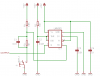
It is not really different from what has been suggested, except it uses the venerable 555. The original circuit is from an MIT link that is now broken. This gives a positive pulse with a negative (N.O.) input.

555pulse-png.52885


Obviously, the component values can be modified to give whatever pulse width you want.

John
 

Attachments

  • 555pulse.png
    555pulse.png
    6.4 KB · Views: 1,427
Yes, I know, a monostable is the other way to go. I want to build both of these into my project and "race" them to see which is better at switch debouncing.

The advantage of the Schmitt trigger solution is, of course, simplicity: I can debounce 4 switches with a quad inverter, where I'd need 4 555s (or 2 556s).
 
Hey, there are lots of ways to do it. I was just givin' you a rough time. Go with the simplest. John
 
No, no, your suggestion was much appreciated. It'll be interesting to see which method gives the best results. The raw pushbutton output is really, really flaky. Cannot drive my circuit (3 flip-flops) with any kind of reliability.
 
But here's my problem: since this uses an inverter, it generates a negative-going pulse (from a negative-going switch closure). That's find and dandy, if you want a negative pulse and if you have a normally-closed switch. But I need the opposite: a positive-going pulse from a normally-open switch.

No it doesn't. As you say -and as the drawing shows - it uses an inverter. A negative going (closing to ground) switch function will generate a positive going output from the inverter.

Which you say is what you need.........
 
I tried it (the Schmitt inverter RC debouncer) and it works great. Ended up using 4.7K, 1K and 1µF. And yes, the chip I used (a xxxLS14) is a hex inverter. Much easier than a 555, although I still want to try that too.
 
Status
Not open for further replies.

Latest threads

New Articles From Microcontroller Tips

Back
Top