Continue to Site

Welcome to our site!

Electro Tech is an online community (with over 170,000 members) who enjoy talking about and building electronic circuits, projects and gadgets. To participate you need to register. Registration is free. Click here to register now.

  • Welcome to our site! Electro Tech is an online community (with over 170,000 members) who enjoy talking about and building electronic circuits, projects and gadgets. To participate you need to register. Registration is free. Click here to register now.

Quick Noobie Help!!!

Status
Not open for further replies.

StormRyda

New Member
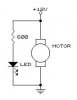
Im going to make this fast so I don't waste to much time. Basically lets say I have 2 devices and a 12 volt battery. One device is a 12 volt Motor, while the other device is a 3 volt LED. Is it possible to put these 2 devices in series and some way make it so that the lightbulb will not burn out? Im not to sure which way the electrons flow from, Positive to Negative? So would adding a resistor between the motor's negative and led's positive lead work? Im not to sure...


Battery Positive ----> Motor Positive
Motor Positive ----> Resistor
Resistor ----> To Led
Led ----> Battery Negative?

Will this work?
Thank you for your time

Basically I am making this circuit so that if the motor dies/fails or something is wrong with the connection the LED will indacate this.
 
In a word no. In a series circuit , the current that the motor draws would burn out the LED. A resistor could lower the available current to where that wouldn't occur but then the motor wouldn't operate. I don't know what you trying to do but if the LED is just an indicator that the motor is on you would connect the motor and the Led w/ a current limiting resistor in parallel.
 
In a series circuit the same amount of current flows through all components. Since the led probably can only take 20ma, that is almost certainly not enough for the motor, so no you probably cannot do it that way.

Electricity flows from negative to positive, but that doesn't matter really. In a series circuit you can add a resistor in whichever position you want and it will do the same thing.

A different way to accomplish it is with a low value resistor in series with the motor. A certain amount of current flowing through it will create a certain voltage drop (ohm's law), so you use a comparator to sense this voltage drop and trigger when the current goes too low. The problem with that idea though is it assumes that when the motor fails it will be open circuit, when it could actually be short circuit, which could be overheat the motor or the drive circuit.
 
TillEulenspiegel said:
In a word no. In a series circuit , the current that the motor draws would burn out the LED. A resistor could lower the available current to where that wouldn't occur but then the motor wouldn't operate. I don't know what you trying to do but if the LED is just an indicator that the motor is on you would connect the motor and the Led w/ a current limiting resistor in parallel.

How would i accomplish this? Like i said I am ok at this stuff...but never done anything that has a current limiting resisteor in parallel? Could you quickly draw up a circuit diagram if thats not a problem? I kinda get what ur saying..
 
Something like this ...
 

Attachments

  • motor_298.jpg
    motor_298.jpg
    7.2 KB · Views: 487
jbeng said:
Something like this ...
This won't indicate motor failure. It just indicates that the supply voltage is applied to the motor. To indicate motor open or motor stalled, you need a series current sense resistor and a window comparator, or a tachometer.
 
Ron H said:
This won't indicate motor failure.

True, true ... I got ahead of myself there ... :oops:
 
Status
Not open for further replies.

New Articles From Microcontroller Tips

Back
Top