Hello, I am new here, and got two question regarding capacitor and errors...
Question 1:
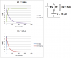
I recently did an experiment where I charged and discharged a capacitor to estimate its capacitance (by getting voltage vs. time and the time constant).
Now, ideally, the charging and discharging rates would be same and produce same shaped exponential growht/decay curves on voltage vs. time graph... however, the charging occurred more rapidly and has a time difference of about 100 s (in comparison to discharge, which was slow)...
What could be the source of the error?... why did the charging and discharging rates differ with charging being so much faster?
Question 2:
In a similar experiment, I changed the resistor that was on the circuit and decreased the resistance of the circuit (500 kΩ to 10 kΩ) to have two different estimates of the time constant and hence, estimate two of same capacitance... Now, the first one came out to be close to the actual capacitance value of about 33µF, but the second estimated capacitance (from decreased resistance) was about 600 µF... (6 V battery was used, by the way).
Again, what could be the source of error? As the estimation was based on the graph (first question), could it be from the human errors from recording the data or is there other electronic sources of error?
Thank you in advance.
Question 1:
I recently did an experiment where I charged and discharged a capacitor to estimate its capacitance (by getting voltage vs. time and the time constant).
Now, ideally, the charging and discharging rates would be same and produce same shaped exponential growht/decay curves on voltage vs. time graph... however, the charging occurred more rapidly and has a time difference of about 100 s (in comparison to discharge, which was slow)...
What could be the source of the error?... why did the charging and discharging rates differ with charging being so much faster?
Question 2:
In a similar experiment, I changed the resistor that was on the circuit and decreased the resistance of the circuit (500 kΩ to 10 kΩ) to have two different estimates of the time constant and hence, estimate two of same capacitance... Now, the first one came out to be close to the actual capacitance value of about 33µF, but the second estimated capacitance (from decreased resistance) was about 600 µF... (6 V battery was used, by the way).
Again, what could be the source of error? As the estimation was based on the graph (first question), could it be from the human errors from recording the data or is there other electronic sources of error?
Thank you in advance.