Ubergeek63,
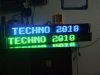
thanks for the input, I would love to try your ideas as well but alas you chimed in after I had decided what chips to buy, and bought them. There will be plenty of opportunity though as I will have over 2500 left over LEDs after this matrix is complete, which has 1474 LED's divided between two separate matrices.
however, until I am done with this matrix, I will be working on this design that you despise with decent reasoning, so instead of new hardware how about so suggestions on this particular design? Like some odd things you should be given, this LED matrix is huge in size, the longest pathway of power for the farthest LED from a closed power source is about 16 feet from source to LED to sink. Each matrix will be just over 700 LEDs controlled by separate ATMEGA2560 chips. Two 6.4v 15 amp power supplys will feed the two matrices. There are plenty of other weird things about this matrix shape and size as well.
What I am more interested in at this point is getting the subroutines operating in the programming. The ISRs and row data senders etc.
")