Continue to Site

Welcome to our site!

Electro Tech is an online community (with over 170,000 members) who enjoy talking about and building electronic circuits, projects and gadgets. To participate you need to register. Registration is free. Click here to register now.

  • Welcome to our site! Electro Tech is an online community (with over 170,000 members) who enjoy talking about and building electronic circuits, projects and gadgets. To participate you need to register. Registration is free. Click here to register now.

Questions about capacitance multiplier in PSU.

Status
Not open for further replies.

xiongyw

New Member
hi, all,

I am reading an article by Rod Elliott titled "A Simple Capacitance Multiplier Power Supply For Class-A Amplifiers", located here:

**broken link removed**

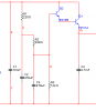
I have a question regarding the purpose of the 12k resistor in Figure 3:

**broken link removed**

The text says the following about this resistor, but I don't get it:

"The resistor to ground stabilises the circuit against variations in transistor gain, but increases dissipation slightly. This is done deliberately to ensure that there is sufficient voltage across the multiplier to allow for short term variations."

How this resistor to stablize the gain? e.g., what's the cause of the variation of the gain, and how this resistor to cure it?

thanks.
 
The 12kΩ resistor does control gain. Think of it as this: The more resistance you apply will lower the gain and also the other way around.
 
EDIT: I see the reason now. It is to lower the base voltage so there is enough voltage drop across the transistors to eliminate the ripple. It has nothing to do with "gain" as an emitter follower has a gain of 1 or less.

by me said:
I see no reason for the 12K resistors. You could move it to the same position as the load and use it as a bleeder resistor to discharge all the caps on power off if there was no load connected.
 
Last edited:
EDIT: I see the reason now. It is to lower the base voltage so there is enough voltage drop across the transistors to eliminate the ripple. It has nothing to do with "gain" as an emitter follower has a gain of 1 or less.

I am still missing the point that how the resisitor lower the base voltage.

Enclosed is a simplified circuit segment, where R3 is the 12K resistor. So the point is that adding R3 will lower the voltage of node 9. Is the following thinking correct:

The supply rail is relative DC, so the impedance of C3 is very big (approaching infinity), so it will divide most of the voltage on C2, leaving less for R2. By paralleling with R3, the impedance is dropped to below 12K, so it (together with R3) will divide less voltage as before?

If this kind of thinking ok, then introducing R3 may also cause C3//R3 to share more some AC (ripple) component than C3 alone. If this is true, then is this what we wanted?

The next question is that, why lowering the base voltage can stablized the circuit (or reduce the ripple)?

Thanks.
 

Attachments

  • cap_mul.PNG
    cap_mul.PNG
    7.3 KB · Views: 684
I am still missing the point that how the resisitor lower the base voltage.
Lets say that the average rectified voltage across C1 is 20V. If you ignore the transistors for the moment you'll see that you have a voltage divider made up of the 3 resistors. 1.6ma will flow through all the resistors (20V / 12440Ω) meaning that there will be 19.65V across C2 and 19.3V across C3.
The next question is that, why lowering the base voltage can stablized the circuit (or reduce the ripple)?
Now there is ripple across C1 and this may mean that the voltage there really varies between 19 and 21V depending on the load.
The following assumes a perfect transistor with infinite beta. The real case would be different. If the base of the first transistor was steady at say 20V that would mean that the collector would need to be at least above 19.3V for the emitter to remain steady at 19.3V. If the collecter drops below 19.3V then the emitter does also thus letting the ripple through. But if the base was at a lower voltage, then the emitter voltage will be lower allowing more ripple on the collector before the emitter voltage drops out.
 
Last edited:
Lets say that the average rectified voltage across C1 is 20V. If you ignore the transistors for the moment you'll see that you have a voltage divider made up of the 3 resistors. 1.6ma will flow through all the resistors (20V / 12440Ω) meaning that there will be 19.65V across C2 and 19.3V across C3.
Now there is ripple across C1 and this may mean that the voltage there really varies between 19 and 21V depending on the load.
The following assumes a perfect transistor with infinite beta. The real case would be different. If the base of the first transistor was steady at say 20V that would mean that the collector would need to be at least above 19.3V for the emitter to remain steady at 19.3V. If the collecter drops below 19.3V then the emitter does also thus letting the ripple through. But if the base was at a lower voltage, then the emitter voltage will be lower allowing more ripple on the collector before the emitter voltage drops out.

Thanks a lot for the elaborated explanation.

So the point is to give more headroom for Vce to "encapsulate" the ripple (or prevent the ripple from appearing on Ve). For the purpose of lowering the base voltage (i.e., making more headroom), will increasing R1/R2 (instead of introducing R3) an alternative?

Also, will the adding of R3 introduce a bit more ripple on the base? I mean that adding R3 into the divider (as you describled) causes R3 directly "see" the ripple (through the other two resistors), and it divides the most part of the DC as well as the ripple (since it's resistance is much bigger)...Or this effect is "smoothed" by the caps somehow, and can be ignored as compared to ripple on the supply rail?

Thanks again,
/bruin
 
Last edited:
Hi,

The circuit shown in the first post is a capacitance multiplier yes, but those kind
of circuits are dated. Here's why...

The power supply ripple is objectionable and so by filtering the base voltage
separately, a more stable voltage is applied to the base and so the emitter
follower can produce a voltage that is more stable, but that stability comes only
in the form of a more stable *AC* voltage (less ripple). This is because the
cap acts to reduce the ac output voltage.
In the more modern age, zeners are often used at the base to help provide
both better AC stability *and* DC stability too. Thus, by using two zeners
biased in a similar fashion you can get both low ripple and some dc regulation as
well.

The only time the capacitance multiplier will be better than a zener regulated
version is when the input voltage fluctuates so wildly that it will sometimes
drops below the zener voltage, or power dissipation has to be kept to a minimum
(although later circuits will still have to deal with that). If the voltage drops
below the zener voltage however then there is something else probably wrong
anyway.
 
Last edited:
For the purpose of lowering the base voltage (i.e., making more headroom), will increasing R1/R2 (instead of introducing R3) an alternative?
Only under heavy loads where more base current will be drawn. Not a good idea because it degrades the regulation of the supply. As per MrAL's explanation, adding zener diodes would give voltage regulation also and are the more common method used in a circuit like this.
Also, will the adding of R3 introduce a bit more ripple on the base?
No. The caps, C2 & C3 are what reduce the ripple on the base. R3 has very little effect on ripple.
 
Status
Not open for further replies.

Latest threads

New Articles From Microcontroller Tips

Back
Top