Continue to Site

Welcome to our site!

Electro Tech is an online community (with over 170,000 members) who enjoy talking about and building electronic circuits, projects and gadgets. To participate you need to register. Registration is free. Click here to register now.

  • Welcome to our site! Electro Tech is an online community (with over 170,000 members) who enjoy talking about and building electronic circuits, projects and gadgets. To participate you need to register. Registration is free. Click here to register now.

Question on PWM - 16F627A

Status
Not open for further replies.

demestav

Member
Hello everybody.

I was reading tonight about the PWM module of the pic.

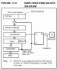
Reading the manual, it says that duty period is set by PR2. PR2 is 8 bits. After that is says that duty cycle is set by CCPR1L and 2 bits from CCP1CON making a total of 10bits.

Questions:
1) Since duty cycle is a fraction of the duty period which is 8-bits, how come its 10bits?

2) There is a comparator between timer2 and CCPR1H to decide when it is the end of the duty cycle. Timer2 is 8bits and the 2 LSBits are coming from the prescaler (manual). But if it is coming from the prescaler it means that those 2 bits are always constant right? I dont really get this.


Thank you for reading. Any help would be appreciated!!!
 
This confuses many people. The short answer is that PR2 uses Tcy timing while the 10-bit CCPR1 register combination is using Tosc timing.

If for example you're using a 4-MHz clock, Tosc is 250-nsecs and your Tcy instruction cycle time is 1.0-usecs.

If you ignore the two least significant bits of the 10-bit CCPR1 value you've effectively divided the duty cycle value by 4 and the 8-bit CCPR1H value represents 1.0-usec (Tcy) duty cycle counts which is the same time scale used by the PR2 register.
 
Last edited:
Hello Mike and thanks for your reply!

Something is indeed a bit confusing! Please help me out!

Ok. To define the duty period you set the PR2 register which is compared with TMR2 value. PR2 is constant and TMR2 value is changing every Tosc * 4 . I think we agree to this.

However, for the duty cycle, CCPR1H combination, is again constant which is compared with the changing TMR2 value right? But TMR2 as we said before is changing every Tosc *4.

???

Thanks!
 

Attachments

  • fig.jpg
    fig.jpg
    28.5 KB · Views: 211
Actually, if you read Note 1 in the diagram you posted you'll see that Timer 1 is concatenated with 2 bits from the Q clock so it's really running at Tosc and not Tosc * 4.

I apologize. I understand how it works but I'm afraid I'm not very good at explaning concepts to people. Perhaps someone else will jump in with a better analogy to helps us out.

Take care. Have fun. Kind regards, Mike
 
Take TMR2 (8 bits) and append Q clock (2 bits or intenal prescaler 2 bits) and you have a 10 bit value.

So TMR2 becomes 10 bits for its value.
 
Hello and thank you both for your answers.

mramos1 I read that. However, I dont understand it. Timer2 is incrementing on it's own, isnt it? How come, 2-bits from the Q-clock are appended? And also what does it means 2-bits from the internal prescaler?
 
I thing you're confusing yourself?.

You are essentially setting two different things:

1) The frequency it runs at.

2) The duty cycle.

These are completely different, and don't affect each other.
 
Ok look. Because it is indeed very confusing for me and I would like to clear it out, lets take it slowly.

Ok the image I have attached above says:
"8-bit timer is concatenated with the 2-bit internal Q clock, or 2 bits of the prescaler to create 10-bit time-base."

SO! What I understand from here. We take the 8-bits of the timer2 and we append to the LSB 2 bits of the prescaler. This is what does not makes sense to me. Let's say the timer2 value is 00001010 and the prescaler is set to x4 (which is 01 on T2CON). By applying what the previous sentance says, the value of our 10bit timer should be:

00001010 (timer2) + 01 (prescaler) = 0000101001

????? So what would be the value of the timer at the next instruction cycle?????
 
Sorry but, is this really as this important?

To me, just using the datasheet formula to make it work is enough. Oh well, maybe because i'm only a french Canadian and just want to make it work as it's suppose to.

If you want to make things easy, just use my PicMultiCalc software and apply the value in your program.

**broken link removed**
 
demestav said:
00001010 (timer2) + 01 (prescaler) = 0000101001

????? So what would be the value of the timer at the next instruction cycle?????

In the above example the next value will be 00001010 + 10, then 00001010 + 11 then 00001011 + 00 etc. These increments therefore happen at 4 times the speed that Timer2 gets incremented. I'm assuming in the above example that the prescaler is set to 4.

The concatenation adds together Timer2 + Timer2 Prescaler + internal clock divider. So, if the prescaller was set to 32 then the following would be incremented.

First the 2 internal clock divider bits are incremented. (2 bits)
If there is an overflow from above then the prescaler is incremented. (5 bits)
If there is an overflow from the prescaler then Timer2 is incremented. (8 bits)

The top 10 bits are used in the comparison. In this case Timer2 + the two most significant bits of the prescaler.

If the prescaller is set to 2 which is only 1 bit then the 10 bits are Timer2 (8 bits) + Prescaler (1 bit) + Internal Divider(1 bit).

Mike.
 
mister_e said:
Sorry but, is this really as this important?

To me, just using the datasheet formula to make it work is enough. Oh well, maybe because i'm only a french Canadian and just want to make it work as it's suppose to.

It is nice to understand how it is working isn't ! :)

Pommie said:
The concatenation adds together Timer2 + Timer2 Prescaler + internal clock divider. So, if the prescaller was set to 32 then the following would be incremented.

First the 2 internal clock divider bits are incremented. (2 bits)
If there is an overflow from above then the prescaler is incremented. (5 bits)
If there is an overflow from the prescaler then Timer2 is incremented. (8 bits)

The top 10 bits are used in the comparison. In this case Timer2 + the two most significant bits of the prescaler.

If the prescaller is set to 2 which is only 1 bit then the 10 bits are Timer2 (8 bits) + Prescaler (1 bit) + Internal Divider(1 bit).

Mike.

Hmmm. Thanks about the info (although I dont fully understand it). Where did you get this info from?
 
Status
Not open for further replies.

Latest threads

Back
Top