Electro Tech is an online community (with over 170,000 members) who enjoy talking about and building electronic circuits, projects and gadgets. To participate you need to register. Registration is free. Click here to register now.
Welcome to our site! Electro Tech is an online community (with over 170,000 members) who enjoy talking about and building electronic circuits, projects and gadgets. To participate you need to register. Registration is free. Click here to register now.
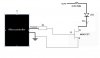
I am to design a circuit to light up a LED at the O/P of the microcontroller. What possible component can i add in the circuit to light up the 3V/2A LED.
Output voltage is 12V.
Tuck3rz,
I will do my best to help you understand....
A MOSFET (metal oxide semiconductor field effect transistor), or any transistor can act like a switch.
Which is what it will be doing here in your circuit.
The "gate" (aka 'base') only requires a minute amount of current to effectively 'switch' the mosfet/transistor on. That is what the 1K resistor is for. To heavily limit current.
This is what your microcontroller will do. When you 'set' the ouput (logic 1), the MOSFET will turn on, allowing current to flow through the Drain to the Source (or if it were a transistor from the collector to the emmiter)
To put it simply,
- Output of Microcontroller goes high,
- MOSFET turns on (closes)
- Current flows from your 12v source through the big resistor, through the LED, through the MOSFET, to ground.
The low resistance resistor (4.7R @ 25W) is there to limit current seen as though the LED and MOSFET dont have much resistance...
It is only a small amount of resistance to allow a large amount of current to flow. That is why it needs to be rated at least 25W, becasue there will be alot of current passing through it.
Hope that makes it abit clearer....
2A LED hey... that one massive LED...
Got a photo? hope you dont mean .2A or even 2mA???
Im not sure if the 4.7R resistor will limit to exactly 2A.
I dont know if ericgibbs worked it out, and neither did I.
Not sure if you need to work that out properly. The basic circuit is correct. But the values may need tweeking.
Use ohms Law to work out the right value resitor to limit to 2A.
Yes, the lecturer should have changed the LED current to 20mA instead. It was an unrealistic circuit with a 2A LED and my guess was that it was a typo and should have read 20mA. He's now realised his mistake but chose to reduce the resistor to 200mΩ and you now have the worlds most powerful LED of 100W.
A normal circuit would drive an LED at 2V and 20mA via a 150Ω resistor from a 5V supply. I think what the lecturer intended was something similar but it somehow got confused.
This site uses cookies to help personalise content, tailor your experience and to keep you logged in if you register.
By continuing to use this site, you are consenting to our use of cookies.