Continue to Site

Welcome to our site!

Electro Tech is an online community (with over 170,000 members) who enjoy talking about and building electronic circuits, projects and gadgets. To participate you need to register. Registration is free. Click here to register now.

  • Welcome to our site! Electro Tech is an online community (with over 170,000 members) who enjoy talking about and building electronic circuits, projects and gadgets. To participate you need to register. Registration is free. Click here to register now.

Question about PCB transformer

Status
Not open for further replies.

justin_t

New Member
Hi

I have a small PCB used to control a 240VAC heater and motor.

There is a low voltage control circuit on the board including a micro-controller.

To produce the low voltage required, the following equipment is used.

1 x Hahn transformer 230V 50-60 Hz (BV EI 304 2086)
Sek 1: 9 V 1.05 VA
Sek 2: 9 V 1.05 VA

This is fed through a fairly standard surface mount rectifier and then on to a 5 Volt regulator.

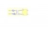
On both the live and neutral lines from mains supply to the transformer, there is a 100 ohm surface mount 1206 resistor, these are what have raised a query.

I had never taken much notice of them until now as i need to update the saftey testing file and need approvals for all componets that are exposed to the mains. The rating of any resistor like this that i have looked at are all in DC....

Does anyone know why these resistors would be here on the AC input to a transformer. And do they need to be special resistors to use in an AC line?

Is it a strange set up or fairly standard?

Ive attached a picture of the arrangement on the circuit diagram for reference.

any help appreciated

justin
 

Attachments

  • transformer.JPG
    transformer.JPG
    27.4 KB · Views: 156
I'm guessing that the chip resistors are used as fuses...

Say that a short develops on the secondary of the transformer (shorted diode?). The excessive current coupled into the transformer primary will heat the chip resistors to the point that they will either burn open, or melt their solder attachment and they will fall off the PC board :D
 
Why would they be on both the live and the neutral? Unless it's two phase power in, or would it just be paranoia of a live/neutral short?
 
Why would they be on both the live and the neutral? Unless it's two phase power in, or would it just be paranoia of a live/neutral short?

A lot of idiots cut the round pin (GND) off a standard line cord. That lets you plug the resulting two prongs into LI/N either way. If the plug is reversed, the other side of the transformer primary could have L1 on it...
 
Yeah, I've done that a few times (cut the saftey ground off) though I knew at the time it was safe. Almost all electrical outlets in the US now are polarized, the left blade is longer than the right blade, this however doesn't prevent the normal stupid electrician errors from occurring, so I guess it's good paranoid engineering.

Build an idiot proof device and nature will build a better idiot.
 
Last edited:
Hi

I have a small PCB used to control a 240VAC heater and motor.

A lot of idiots cut the round pin (GND) off a standard line cord. That lets you plug the resulting two prongs into LI/N either way. If the plug is reversed, the other side of the transformer primary could have L1 on it...

Yeah, I've done that a few times (cut the saftey ground off) though I knew at the time it was safe. Almost all electrical outlets in the US now are polarized, the left blade is longer than the right blade, this however doesn't prevent the normal stupid electrician errors from occurring, so I guess it's good paranoid engineering.

It's a 240 V device, we don't know in which country or which type of plug is used... It may be polarized or not.

Build an idiot proof device and nature will build a better idiot.
Including the :eek:electrician:eek:? that wires a socket the wrong way :D
 
Last edited:
I guess those two resistors are built in for better sales. Using a fuse will do the same job with the exception that it can be changed easily.

The transformer in my electrolytic plating station had a thermofuse (non resettable) mounted directly at the transformer core. That thing blew up some day and consequently I had to purchase a new transformer. (€ 138)

Protective earth is not required if the overall design of the device is well isolated (no metal parts in the enclosure)

Boncuk
 
Thanks for the comments.

I can understand why they put a "fuse" in each line. Infact for this PCB to meet the CE safety standards, the main supply on the PCB has a fuse in each line on the board as the unit will not definetly be installed by a qualified electrician and there may be a case where they mix the live and neutral wires up (UK and Europe) and an earth fault on the live in either set up will blow the live fuse.

However the case has arose in the past where the fuse in the neutral line blew 1st. This meant that although the PCB appears to be dead with a blown fuse. The board is still live via the live intact fuse. I sometimes question the safety peoples reasoning...

In terms of the above discussed resistors, I guess I will now need to find a 1205 100 ohm resistor that is rated to 240 VAC...
 
Status
Not open for further replies.

Latest threads

New Articles From Microcontroller Tips

Back
Top