Hello,
I dont understand why when using a quarter wave transformer, all power is delivered to the load.
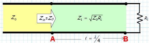
I understand well that in point A, Zin(A) equals to Zo, and therefore there's no reflection - Γ(A)=0.
Moreover the quarter-wave lenght line is lossless and therefore it absorbs no power.
But why is the reflection coefficient in point B disregarded?
Zin(B) = RL ≠ √(ZoRL), Therefore some of the power delivered to the load is reflected and retreats towards point A, and back to the generator.
So there's still some power going back to the generator, isnt it?
I dont understand why when using a quarter wave transformer, all power is delivered to the load.
I understand well that in point A, Zin(A) equals to Zo, and therefore there's no reflection - Γ(A)=0.
Moreover the quarter-wave lenght line is lossless and therefore it absorbs no power.
But why is the reflection coefficient in point B disregarded?
Zin(B) = RL ≠ √(ZoRL), Therefore some of the power delivered to the load is reflected and retreats towards point A, and back to the generator.
So there's still some power going back to the generator, isnt it?
Attachments
Last edited:
