Continue to Site

Welcome to our site!

Electro Tech is an online community (with over 170,000 members) who enjoy talking about and building electronic circuits, projects and gadgets. To participate you need to register. Registration is free. Click here to register now.

  • Welcome to our site! Electro Tech is an online community (with over 170,000 members) who enjoy talking about and building electronic circuits, projects and gadgets. To participate you need to register. Registration is free. Click here to register now.

Quad opamps

Status
Not open for further replies.

Kranthikkenoch

New Member
Hi everyone,
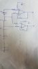
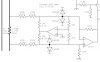
I'm desiging a monitoring circuit using mc34074, can I give an input voltage of +44v to the quad opmp and find the difference between top 2 cells?
 
No, no higher than 44-2.2 = 41.8V over the full temperature range.

cmr.png
 
upload_2017-6-29_6-25-38.gif

Depending on resistors and gain:
(V2-V1)* gain = Vout-0V
So if V1, V2 are the ends of the top battery, and gain is set to 0.1 then Vout is the top battery/10.
If all resistors have the same value; Gain=1, Va and Vb are at 1/2 V2 voltage, and Vout is V2-V1
.....(Because Va, Vb are lower in voltage the "input voltage" of the amp is less of a problem)
-----edited-----
You must be trying to run the amp at a 44 volt supply.
By using a circuit like above, with a very low gain, you can choose a 5V or 12V amp and get good results.
Remember, (from post #2) the inputs can not run from (-)supply to (+)supply and work.
 
Last edited:
If you are willing to use Linear Tech components, they have some "over the top" opamps whose input voltage may be higher than its supply voltage.
 
This is the circuit I'm trying,all equal resistors and the output will be a max of 4V,can I give these voltages(36V and 32v) as my input voltages or the input voltages are restricted between +22v and -22v.
 

Attachments

  • op.gif
    op.gif
    8.3 KB · Views: 125
If the four resistors are equal, and the inputs are as shown, then output is not 4V!

If the inputs are as shown, the output is 4V, the four resistors cannot be equal!

What are you really trying to do? Give us the specs of the circuit you want, not a solution that doesn't work.
 
Your opamp has no power supply so it will do nothing.
The datasheet says that its input voltages must not exceed its power supply voltages and the common mode range is the range of voltages where the inputs work properly.
 
I have a Li ion battery pack which is 9s 4p i.e, 36V. I have to monitor the voltage of each individual cell. So I came up with this circuit of Differential amplifier where I connect my battery pack to the opamps to know the votalges as shown in pic. I have tried LM324 earlier to monitor 24V battery pack, but now as I wanted to have a larger battery pack and voltages are high I wanted to know if the IC MC34074 quad opamp will do the job (VCC of 36V and Vee 0V)
 

Attachments

  • 20170629_230045.jpg
    20170629_230045.jpg
    454.5 KB · Views: 109
A Lithium rechargeable cell is 4.2V when fully charged so 9 make 37.8V, not 36V.
Your circuit will work fine with a 36V and 0V supply (still not shown on your schematic), equal value resistors and an MC34074 quad opamp.
 
With the circuit you show in post #5, with equal resistors, the input I2 has to range from 36V to 40V so that the output ranges from 0V to 4V. Is that what you want?
 
MikeMl the voltages are mentioned wrong in the post #5, please refer my new circuit post #8 which is the actual thing that I'm trying to do(to monitor the voltages of each individual cell)
 
Note that the resistor matching tolerance has a significant effect on common-mode offset in that circuit.
Thus for 1% resistors the output offset can be as much as 1% * 36V = 0.36V for the top op amp, that is, the output could be in error by 0.36V.
So you likely want to use a resistor network that is matched to 0.1% or better.
 
MikeMl the voltages are mentioned wrong in the post #5, please refer my new circuit post #8 which is the actual thing that I'm trying to do(to monitor the voltages of each individual cell)

In the circuit of #8, if the input voltages are as shown, the opamp only needs to be powered on ~20V, because the inverting and non-inverting inputs will be at a maximum of 18V, and the output will be at 4V.

I agree with Cruts that the resistors need to be matched to better than 0.1%
 
Note that the resistor matching tolerance has a significant effect on common-mode offset in that circuit.
.

Cruts beat me on this response.
Indeed, the most difficult part is getting a tightly matched resistor network, which also tracks with temperature.

Again, Linear Tech offers a solution. https://www.linear.com/parametric/precision_resistor_network

Note: I'm not affiliated with them....I only mention them often because they have some outstanding linear products.
If you go to their website, look for design note DN 1023. It explains, in excruciating but glorious detail, the imperatives of using tightly matched resistors in a high-CMRR application.
 
Last edited:
This circuit can be handy for measuring relatively small voltages a long way from ground (ie, a large commong mode voltage). It's described in Horowitz & Hill but I've not been able to find a decent diagram of it... please excuse this scruffy snippet cut from a schematic I drew years ago. In this case it's used as a high-side current sense.

The idea is that the first op-amp servos the common-mode voltage to zero but leaves the differential mode unchanged because it is coupled equally to the positive and negative input signals. It's then followed by a conventianal differential amp, but this can have a higher gain than would otherwise be the case, because it's not necassary to attenuate the common-mode voltage to within the input range of the op-amp.

It's probably not necassary for this application (which I'm sure is why no-one else has mentioned this yet), but worth bearing in mind.
 

Attachments

  • diff1.png
    diff1.png
    41.2 KB · Views: 117
Thank you everyone, I have implemented the circuit and the outputs are also almost accurate as I have used 100 kohm 0.1% resistors, but the problem is my quad opamp gets hot, is that okay? or should I change my resistor values?
 
Last edited:
My general rule of thumb is, unless its a woman then hotter is not better
 
In the schematic in post #5, the inputs are reversed. For a positive voltage output, the non-inverting input must be greater than the inverting input.

ak
 
An overloaded opamp gets hot. Also an opamp that is oscillating at a high frequency caused by stray capacitive coupling between the rows of contacts and wires all over the place on a solderless breadboard. The wires on the breadboard act like antennas for interference and AM radio stations.

You never showed us your resistor values that might be overloading the opamps and never showed any power supply decoupling.
 
Status
Not open for further replies.

Latest threads

New Articles From Microcontroller Tips

Back
Top