Continue to Site

Welcome to our site!

Electro Tech is an online community (with over 170,000 members) who enjoy talking about and building electronic circuits, projects and gadgets. To participate you need to register. Registration is free. Click here to register now.

  • Welcome to our site! Electro Tech is an online community (with over 170,000 members) who enjoy talking about and building electronic circuits, projects and gadgets. To participate you need to register. Registration is free. Click here to register now.

pwm using TMR0 problems

Status
Not open for further replies.

jeremygaughan

New Member
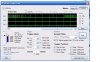
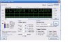
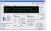
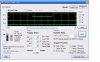
I'm using TMR0 to make PWM. I read the ADC then put a value in a folder. I then turn the output bits on with every interrupt then check throughout the program to see if the timer has exceeded the values from the adc. If I add the timer and the value from the adc together and they trip the flag then I turn them off. The problem I'm having is that the PWM only works for about half of the pot. I have 5k pots on both sides of the 10k to fine tune and I also get good adc resolution using other programs with this same circuit. So I believe the problem to be in my program. I have included the program and a few webshots of what the pickit analyzer is seeing on the output pins. I get what I'm seeing, but I have no idea how my program is doing that. It's like the ADC is affected by the TMR0. Any ideas?

Code:
;learning to do pwm with tmro 12f675


	list P=12f675
#include <p12f675.inc>
	__config _INTRC_OSC_NOCLKOUT & _BODEN_OFF & _WDT_OFF & _PWRTE_ON & _MCLRE_OFF & _CPD_OFF & _CP_OFF 
	ERRORLEVEL -302
	
	cblock		20h
	pwmcounter, channel1, channel2
	endc

	ORG		0000h
	goto	setup
	
	ORG		0004h
	movlw	0x03		;interrupt turns on motors then
	movwf	GPIO		;call pwm keeps checking to see it's
	BCF		INTCON,2	;time to shut them off
	RETFIE				;reset interrupt
	

setup
	bsf		STATUS,RP0	;bank 1
	movlw	0x3c
	movwf	ANSEL
	movlw	0x3c
	movwf	TRISIO		;set I/O
	movlw	0xd8		
	movwf	OPTION_REG	;set tmr0
	bcf		STATUS,RP0
	movlw	0x07		;turn off comparitors
	movwf	CMCON
	movlw	0xa0
	movwf	INTCON		;set interrupt 

start
	movlw	0x09
	movwf	ADCON0
	call	pwm
	call	pwm
	call	pwm
	call	pwm
	bsf		ADCON0,1
	call	pwm
	
waiting
	btfsc	ADCON0,1
	goto	waiting
	call	pwm
	call	pwm
	call	pwm
	call	pwm
	movf	ADRESH,0
	movwf	channel1
	movlw	0x0d		;change to read channel 2 potentiometer
	movwf	ADCON0
	call	pwm			;time for adc recharge
	call	pwm
	call	pwm
	call	pwm
	bsf		ADCON0,1

waiting2
	btfsc	ADCON0,1	;waiting for adc
	goto	waiting2
	call	pwm
	call	pwm
	call	pwm
	call	pwm
	movf	ADRESH,0
	movwf	channel2
	call	pwm
	call	pwm
	call	pwm
	call	pwm
	goto	start

pwm
	movf	channel1,0
	addwf	TMR0,0
	btfss	STATUS,C		;test flag if set then turn off GPIO,0
	bcf		GPIO,0
	
	movf	channel2,0
	addwf	TMR0,0
	btfss	STATUS,C
	bcf		GPIO,1
	return
	
	end
 

Attachments

  • lowpwm.JPG
    lowpwm.JPG
    62.9 KB · Views: 214
  • pwmhigh.JPG
    pwmhigh.JPG
    61.7 KB · Views: 247
You may be making this more difficult then it needs to be.

You did not give very good instruction about what you are doing. Is one pot to change the freq and the other the duty cycle?

The following is a way to do fixed frequency. The duty cycle will be whatever percent you set variable duty to. You can read the ADC in the main loop to figure out what that should be.

Declare a duty var to hold the wanted duty cycle
and a dutyCount for the number of interrupts so far in this duty cycle.
Setup TMR0 to interrupt 100 times per PWM period

The interrupt routine should look like this. Yes it is C like AND UNTESTED but I am not about to do it in assembler. Just know that == is a test for equals and that all code inside a { } pair are executed as a block.

Code:
 dutyCount=dutyCount+1;
 // set TRMO IF to zero here
 if (duty==0) 
 {
     GPIO.PWM_PIN = 0;  // zero duty cycle, make sure output is low
 }
 else  // duty cycle is other then zero
 {
     if (dutyCount==100)  // wrap back to zero and turn on PWM_PIN
     {
         dutyCount=0; 
         GPIO.PWM_PIN=1;
     }
     else if (dutyCount == duty)  // enough on time turn off PWM_PIN
     {
         GPIO.PWM_PIN=0;
     }
 }
 return_from_interrupt;

All you need to do is set things up then read the ADC in the main loop and use the value read to adjust duty. But you need to scale the read ADC value to be between 0 and 100. This could have been part of the problem with your original code.
 
Last edited:
as far as I can tell that is what I am doing.
I'm using two channels and each pot is a separate channel with it's own led. There are other small pots there to fine tune.

I use TMR0 as my period
at interrupt I turn on bit 0 and bit 1 which are hooked to leds
I test every few instructions, see if TMR0 plus the values from adc are over 256
if over the flag is set and I turn that bit off.
I am assuming that the adc uses 0-256 and TMR0 is from 0-256, and that TMR0 interrupt doesn't affect anything else kind of like a consistently occurring subroutine.

For example, if my adc value is 25. TMR0 starting at 0is added to 25. the result is that the flag is not tripped. Then about 5 instructions later I check it again. 5+25 still no flag. All the way until 232+25=256 then the flag is tripped and I turn off that bit.

Maybe there is something with the flags that I'm not doing.
 
Last edited:
Lets start with this. Why are you using a pot/ADC to set the period or frequency? What is this thing you are building? There may be a better way to
do it.

I do not see that you are doing what I suggested.
I set TRM0 to 1/100th of the period.
I use the TMR0 interrupt to check to see if I need to change the PWM line state. You do this by reading the TMR0 register every now and again (polling).
What are you doing with the TMR0 interrupt?

Regardless of what you do get 1 channel of PWM working first.

FWIW my students did this to death last year in C. There are a few different ways to generate PWM starting at all software and ending with PWM hardware present on some PICs. Using the timer is a good solution.
 
I appreciate your help I got it working with the ideas that you gave me. It's really hard for me to understand C but after some research I figured out better what you are showing me.
Now it is full PWM on both channels. The idea that I am doing is to use the stick from a playstation to slowly transition the brightness of two leds independent of one another. They blink a little but that is only a matter of scaling back the ADC value and the period counter. The cool thing is the code is even shorter and simpler that before. Here is the new code

Code:
;learning to do pwm with tmro 12f675

	list P=12f675
#include <p12f675.inc>
	__config _INTRC_OSC_NOCLKOUT & _BODEN_OFF & _WDT_OFF & _PWRTE_ON & _MCLRE_OFF & _CPD_OFF & _CP_OFF 
	ERRORLEVEL -302
	
	cblock		20h
	pwmcounter, channel1, channel2, period
	endc

	ORG		0000h
	goto	setup
	
	ORG		0004h
	call	pwm
	BCF	INTCON,2
	RETFIE				;reset interrupt
	
setup
	bsf	STATUS,RP0	;bank 1
	movlw	0x3c
	movwf	ANSEL
	movlw	0x3c
	movwf	TRISIO		;set I/O
	movlw	0xd8		
	movwf	OPTION_REG	;set tmr0
	bcf	STATUS,RP0
	movlw	0x07		;turn off comparitors
	movwf	CMCON
	movlw	0xa0
	movwf	INTCON		;set interrupt 

start
	movlw	0x09
	movwf	ADCON0
	goto	$+1
	goto	$+1
	goto	$+1
	goto	$+1
	goto	$+1
	goto	$+1
	goto	$+1
	goto	$+1
	goto	$+1
	goto	$+1
	goto	$+1
	goto	$+1

	bsf	ADCON0,1
	btfsc	ADCON0,1
	goto  $-1
        movf	ADRESH,0
	movwf	channel1

	movlw	0x0d
	movwf	ADCON0
	goto	$+1
	goto	$+1
	goto	$+1
	goto	$+1
	goto	$+1
	goto	$+1
	goto	$+1
	goto	$+1
	goto	$+1
	goto	$+1
	goto	$+1
	goto	$+1
	bsf	ADCON0,1
	btfsc	ADCON0,1
	goto	$-1
	movf	ADRESH,0
	movwf	channel2
	goto	start

pwm
	incf	period,1
	btfss	STATUS,Z
	goto	$+2
	clrf	period
	movf	channel1,0
	addwf	period,0
	btfss	STATUS,C
	goto	$+3
	bsf	GPIO,0
	goto	$+2
	bcf	GPIO,0
	movf	channel2,0
	addwf	period,0
	btfss	STATUS,C
	goto	$+3
	bsf	GPIO,1
	return
	bcf	GPIO,1
	return
					
	end
 
Last edited:
Hi,
In short, are you trying to dim the LED using PWM with the analog voltage obtained from the pot?
 
Hi,
In short, are you trying to dim the LED using PWM with the analog voltage obtained from the pot?

I'm also trying to understand what is his requirement?:D

@
jeremygaughan do you need to vary the brightness of two LED when you adjust the two pots independently?

Ex:
When adjusting POT1---->vary the brightness level of LED1

When adjusting POT2---->vary the brightness level of LED2

Is this what you need?
 
Ex:
When adjusting POT1---->vary the brightness level of LED1

When adjusting POT2---->vary the brightness level of LED2

Is this what you need?

You got it. That is exactly what I have done. With the help of the forum I got it right now. When I get a few minutes I'm going to put some better notes on the program and a diagram of my circuit.
Gayan, you remember that I was making an IR airplane? My old receiver was very glitchy. It was always pulsing the motor because it took too long to read the incoming IR signal in between running the PWM for the motor. Now all it does is read the R signal and the interrupt takes care of the PWM. I have it hooked up straight to the leds which will eventually be replaced by a motor and an actuator. I already have a good IR system made now I have to put the IR system with this new PWM code. Soon I'll make this mess presentable and show pics, schematics, and program codes complete and polished.
Now I have to figure out how to scale the pwm faster. Right now I'm at 15 times per second. I want over 20. That seems to be one consensus on DC brushed motor control.
 
Last edited:
That is what I'm having a problem with right now. Is it possible to make the TMR0 PWM timer interrupt more often than every 255? For example start the TMR0 at 100 instead of 0 by writing to the TMR0 at the end of the interrupt? If that works the problem will be to get the adc value scaled to something smaller. I'm sure there is a way to do it. I've heard that if you RRF any folder it divides it by two. Is that true?
 
If, at the end of your ISR, you load d'156' into Timer0 then it will interrupt every 100 counts. You will have to subtract 156 from the value when you read it from Timer0 so that your value will go from 0 to 99.

Mike.
 
That is what I'm having a problem with right now. Is it possible to make the TMR0 PWM timer interrupt more often than every 255? For example start the TMR0 at 100 instead of 0 by writing to the TMR0 at the end of the interrupt? If that works the problem will be to get the adc value scaled to something smaller. I'm sure there is a way to do it. I've heard that if you RRF any folder it divides it by two. Is that true?

Why do you think you need more timer interrupts ?

If it is because you can see it blinking? If so is it blinking very fast but steady or sort of random or in some pattern ?
 
I put it on the pickit analyzer and it is very consistant. It blinks almost exactly 15.6 times per second (as far as I can tell). Here are a few pictures of the analyzer. About that RRF, is that true? It would cut a lot of code out.

The reason I think it needs more interrupts is that on the internet they say in general that 20hz is good for small DC brushed motors.

Pommie I'm for sure going to use that writing to TMR0
 

Attachments

  • pwmlow.JPG
    pwmlow.JPG
    62.3 KB · Views: 185
  • pwmmid.JPG
    pwmmid.JPG
    57.6 KB · Views: 174
I think Jeremy's target is to dim the LED & not to blink.

Jeremy is concentrating only with Timer frequency & not the PWM frequency.You need to concentrate on PWM frequency with the duty cycle to dim the LED.

How many steps you are going to use is it 255?
 
Last edited:
I changed the TMR0 value and it couldn't be smoother. I have leds without flicker and they are completely free of interference and fade independent of each other. Now on to the IR receiver. All I need is to get my next batch of chips!!

3v0 no problem, I appreciate the input you gave, you got me going in the right direction when I was stuck.
 
Last edited:
Jeremy,

If you need it to go faster still then you can double the speed by assigning the prescaler to the WDT. To do this change 0xd8 to 0xd0 where you setup the option register.

Edit, ignore the above, I now see you already have the prescaler assigned to the WDT. Another way to speed it up is to put a larger value in TMR0, something like 200 should do.

Mike.
 
Last edited:
By couldn't be smoother I mean that, it's so smooth that you'd have to be pic to understand if it were smoother. I'm really happy with the result. You guys really gave me a big jump forward with my project. Hopefully I can put this together soon and fly a little plane in my house. Thanks a million
 
By couldn't be smoother I mean that, it's so smooth that you'd have to be pic to understand if it were smoother. I'm really happy with the result. You guys really gave me a big jump forward with my project. Hopefully I can put this together soon and fly a little plane in my house. Thanks a million
Let us know how it goes.
 
Status
Not open for further replies.

Latest threads

Back
Top