Continue to Site

Welcome to our site!

Electro Tech is an online community (with over 170,000 members) who enjoy talking about and building electronic circuits, projects and gadgets. To participate you need to register. Registration is free. Click here to register now.

  • Welcome to our site! Electro Tech is an online community (with over 170,000 members) who enjoy talking about and building electronic circuits, projects and gadgets. To participate you need to register. Registration is free. Click here to register now.

PWM linear-esque fan controller

Status
Not open for further replies.
I have plenty of respect for the mains. If someone skipped over my posts and read everyone elses, you'd think I was about to plug in a power cord with bare wires stuck to my tongue.

Recap:
1) All hazardous voltages are ENCLOSED.
2) Nobody can touch said circuitry.
3) I will not submerge circuitry while bathing.
4) Everything will be fused.
5) All circuitry is enclosed.
6) See #2.

The only POSSIBLE way for someone to get hurt would be for it to be taken apart while it's powered on AND someone touched something they should not have. An isolation transformer would limit the current through said unlucky person, but considering 100ma(?) can kill a person, and this circuit will use about 60ma to create 6w out (probably more due to low power factor), the circuit would be deadly even with it.
 
But the only thing stopping the fan from having mains voltage (But DC) applied to it is an ASSUMPTION that the oscillator is not producing anywhere near a 100% duty cycle.

What if the base / gate of the transistor / MOSFET breaks off and gets shorted to a positive supply ? 100% duty cycle would mean the fan would probably burn out before the fuse went. You're then left with a fan which isn't spinning, but the coils of the fan have mains voltage DC applied to them.

Get where I'm going with that ?

Don't look at it as a "what if ..", look at it as a "when ..".

We are saying this for your benefit, not your friends "who you will tell not to touch it". If you can't be bothered to take the precautions mentioned, you shouldn't be playing around with mains voltage - You may aswell be plugging in a power cable with bare wires stuck to your tongue.
 
Thank you!

That's all you had to say!

Being more to the point than "don't do that, it's bad" lets people make more informed decisions.

I will look some more to find a transformer that will work. If I can't find one though, I will just have to take it as an acceptable risk. Nothing is perfect, there are always compromises. I'm sure my previous monitor (CRT) manufacturer ran through possible failure scenarios where it could start on fire (like mine actually did). However, aside from building fire suppression systems into monitors, there probably wasn't much they could do.
 
hi technogeek,
Sorry to keep chewing on your leg bone;)

BUT the following quote is not technically accurate.

technogeek said:
An isolation transformer would limit the current through said unlucky person, but considering 100ma(?) can kill a person, and this circuit will use about 60ma to create 6w out (probably more due to low power factor), the circuit would be deadly even with it.

With an isolation transfomer the unlucky 'victim' would have to get across BOTH the secondary wires of the transformer,
the isolation transformer would NOT limit the current in that case.

It would however prevent a electrical shock from one transformer secondary wire to Earth.

That is, the isolation transformer is primarily for Line/Phase to Earth protection.

I did ask in an earlier post 'what are you going to reference the PWM pulses from the PIC to?'

Unless you used a opto isolator, the PIC 0V line would be connected to mains Neutral,
or in the event of an incorrectly wired power outlet Line/Phase.:eek:

I realise that the project would be totally enclosed, but you didnt say that earlier on.

You can appreciate that we do not know your level of expertise, so we have to err on the side of safety first and not to dumb it down.

Regards
Eric
 
Last edited:
I don't fully understand how you're going to regulate the voltage to the fan. You need a proper switching regulator (which an inductor), you can't build one with capacitors alone.

ericgibbs said:
Unless you used a opto isolator, the PIC 0V line would be connected to mains Neutral,
or in the event of an incorrectly wired power outlet Line/Phase.

That depends on how the switching regulator is configured. If it uses a bridge rectifier then both the +V and 0V side of the output will float on mains potential pulses of 50/60Hz, the PIC should always be on the same ground, regardless of whether it's floating or not.

Don't worry about the electrical socket being wired the wrong way round; why should there be any more risk of a live-neutral reversal than a live-earth reveral (which would kill people) or an earth-neutral reversal which would only present a hazard under certain conditions.

Also, don't always rely on isolation transformers, they don't provide protection on all appliances, for example microwaves have the neutral side of the secondary side of their high voltage transformer bonded to the case so an isolation transformer won't provide any protection.
 
hi hero

>> That depends on how the switching regulator is configured. If it uses a bridge rectifier then both the +V and 0V side of the output will float on mains potential pulses of 50/60Hz, the PIC should always be on the same ground, regardless of whether it's floating or not.
Don't worry about the electrical socket being wired the wrong way round; why should there be any more risk of a live-neutral reversal than a live-earth reveral (which would kill people) or an earth-neutral reversal which would only present a hazard under certain conditions
.

I would suggest that you draw a diagram of these two statements, relating to a non mains isolated item of equipment, where the 0V/Gnd of the equipment is directly connected to one of the mains input wires.
A classic example is the 'old' TV chassis [no mains transformer].

Regards
Eric
 
Last edited:
Take a look at a typical transformerless poer supply.
**broken link removed**

Both the +V and -V out put terminals will have 50Hz 330V pulses on them with respect to the neutral wire. It doesn't matter which way round the live and neutral are connected, this will always be the case.

If you used a half wave rectifier then the output could be 12V with respect to the neutral but you would only get half the current for a given ballast capacitance.

In short, your PIC should be powered from the same power supply on the same earth as the fan (it doesn't matter whether it floats or not), if not you should use an opto-isolator.

Either way a socket should not be wired in reverse threfore there should be no need to design your circuit with the possibility of the socket being incorrectly wired. Like I said before, if you're worried about the live and neutral being reversed then you should be farmre worried about the live and earh or earth and neutral being reversed, especially the latter as your appliance will work as normal until some other fault occurs like the neutral going open.
 
Last edited:
hi,
Will look over your diagram, thanks

For ref see pdf.
 
Last edited:
hero,
Your drawing with Line & Neutral reversed.

Eric
 
Last edited:
It still makes no difference, the same risk will still occur if the live and neutral were connected correctly.

EDIT:
I'm incorrect as far as the trnasfomerless power supply is concerned, it was a bad example, it is safer to have the neutral on the bridge rectifier and the live before the capacitor.

However you still need to make sure that the PIC is on the same ground as the bridge rectifier, connecting it to the neutral is no good as there will be -13.4V pulses on it with respect to the neutral.

What I was talking about was based on having the voltage reduction after the bridge rectifier, not before. If you connect a non-isolated DC-DC converter to the output of a bridge rectifier the negitive will pulse at about -330V with respect to the neutral and will be just as dangerous regardless of which way you connect the live and neutral.
 
Last edited:
Hero999 said:
It still makes no difference, the same risk will still occur if the live and neutral were connected correctly.

I am sorry, but you are wrong!

Trace thru the circuit and you should see why.


EDIT:
The 0.47uF has an Xc=6772R at 50HZ, so it has a 34mA nominal current flowing from 230Vrms.

The two back to back 16V zeners clamp the low end of the 0.47uF to 16V wrt the Neutral [0V], when the mains are correctly connected.
When the L & N inputs are reversed the 0V is at mains Line potential.

Its important that you understand this, if you plan to use this type of non isolated psu.

Eric

EDITED Again;
Just seen your edit. OK.

Can you post a sketch covering this point, I dont follow your explanation.
What I was talking about was based on having the voltage reduction after the bridge rectifier, not before. If you connect a non-isolated DC-DC converter to the output of a bridge rectifier the negitive will pulse at about -330V with respect to the neutral and will be just as dangerous regardless of which way you connect the live and neutral.
Eric
 
Last edited:
This is what I'm talking about.

Look at the negitive rail and what happens to it with respect to the neutral on negitive cycles, the same will happen to the positive rail on positive cycles. Both rails jump to 325V above/below the neutral at 50Hz even though the potential difference between them remains at 12V.
 

Attachments

  • Bridge Rectifier HV.pdf
    246.1 KB · Views: 194
hi hero,
That circuit could give electrical hazard problems to a user.

But thats not the point I have been making regarding the PWM driver common reference in the way the OP was talking.

If I get the time today, I'll post a sketch of what I think:rolleyes: 
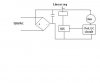
the OP is/was proposing.

Eric

EDIT: Sketch added
 
Last edited:
Now I'm confused...

I'll draw something quick in paint to illustrate my original idea... Apologies for crudeness and lack of time.
 

Attachments

  • smpsfan.JPG
    smpsfan.JPG
    10.9 KB · Views: 149
technogeek said:
Now I'm confused...

I'll draw something quick in paint to illustrate my original idea... Apologies for crudeness and lack of time.
That would probably kill the fan as the peak voltage would still be greater than 16V or whatever the drive electronics are rated to.
 
Status
Not open for further replies.

Latest threads

New Articles From Microcontroller Tips

Back
Top