savvej
Member
PS.note : Question is pertaining dc motor speed and direction control using 8086 uP ,8255,8254 and JK flip flop
According to our Microprocessor textbook,it is said that while using pwm for dc motor speed control,the frequency of the output should be in the range of 60Hz to 1000Hz.
What is it which is causing the limit for the frequency of pwm?
Just to jist the pwm method described in our text bk:
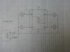
Consider the H bridge,2 inputs say A and B.
when we input A=1,B=0 , motor rotates in one direction(say forward)
when we input A=0,B=1,motor rotates in the reverse direction.
Now we connect A and B to Q and Q' of the flip flop.
//////////////////////////////////////////////////////////////////////////
You may skip this as it just explains how the PWM is generated
///////////////////////////////////////////////////////////////////////////
To the Clr and Preset inputs we connect the 2 timer outputs(counter1 and counter0) from the timer ic 8254.
The timer operates in a mode called rate generator mode,in which supposing that if we load a count of 'n' ,it will be high for 'n-1' clock cyles and then go low for 1 cyle and this constitutes a pulse.Now these pulses are generated continuously once we start the timer.
Now ,what we do is ,say that we connect Clr pin to Cnt1,and start it.Cnt0 output is phase shifted by starting it at a later time.Now what we get at the output of flip-flop is pwm.
/////////////////////////////////////////////////////////////////////////////
so by changing the duty cycle of PWM,motor can be run in
forward fast---forward ---forward slow---stop--reverse slow---reverse--reverse fast
<-----------------------------------------|------------------------------------>
As in we are changing the ratio reverse and forward duration of the motor and thus effective running motor in forward,stop or reverse direction..
===============================================================
Now what I have been using while working microcontrollers in dc motor conntrol,is we use L293D H brige driver IC and used to give just 1 PWM input (In case of driving 1 Motor) to its enable input controlling its speed and direction(using A and B inputs) which I think it better than what is mentioned in the textbook as it gives independent control.
PS.The textbook is followed is The Intel Microprocessor by Barry Brey
According to our Microprocessor textbook,it is said that while using pwm for dc motor speed control,the frequency of the output should be in the range of 60Hz to 1000Hz.
What is it which is causing the limit for the frequency of pwm?
Just to jist the pwm method described in our text bk:
Consider the H bridge,2 inputs say A and B.
when we input A=1,B=0 , motor rotates in one direction(say forward)
when we input A=0,B=1,motor rotates in the reverse direction.
Now we connect A and B to Q and Q' of the flip flop.
//////////////////////////////////////////////////////////////////////////
You may skip this as it just explains how the PWM is generated
///////////////////////////////////////////////////////////////////////////
To the Clr and Preset inputs we connect the 2 timer outputs(counter1 and counter0) from the timer ic 8254.
The timer operates in a mode called rate generator mode,in which supposing that if we load a count of 'n' ,it will be high for 'n-1' clock cyles and then go low for 1 cyle and this constitutes a pulse.Now these pulses are generated continuously once we start the timer.
Now ,what we do is ,say that we connect Clr pin to Cnt1,and start it.Cnt0 output is phase shifted by starting it at a later time.Now what we get at the output of flip-flop is pwm.
/////////////////////////////////////////////////////////////////////////////
so by changing the duty cycle of PWM,motor can be run in
forward fast---forward ---forward slow---stop--reverse slow---reverse--reverse fast
<-----------------------------------------|------------------------------------>
As in we are changing the ratio reverse and forward duration of the motor and thus effective running motor in forward,stop or reverse direction..
===============================================================
Now what I have been using while working microcontrollers in dc motor conntrol,is we use L293D H brige driver IC and used to give just 1 PWM input (In case of driving 1 Motor) to its enable input controlling its speed and direction(using A and B inputs) which I think it better than what is mentioned in the textbook as it gives independent control.
PS.The textbook is followed is The Intel Microprocessor by Barry Brey
Last edited:
 partial)