Continue to Site

Welcome to our site!

Electro Tech is an online community (with over 170,000 members) who enjoy talking about and building electronic circuits, projects and gadgets. To participate you need to register. Registration is free. Click here to register now.

  • Welcome to our site! Electro Tech is an online community (with over 170,000 members) who enjoy talking about and building electronic circuits, projects and gadgets. To participate you need to register. Registration is free. Click here to register now.

PWM DC Motor Control

Status
Not open for further replies.

mark_3094

New Member
Hi,

I want to create a PWM controller for a small DC motor (for academic reasons).
I figured that a 555 timer could create the appropriate pulse.

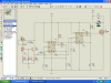
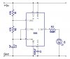
I simply got the 555 LED flasher (attached) and modified it slightly.
* Instead of the LED, I have the motor.
* R1 is 670Ω and R2 is 300Ω
* C2 is 0.1F

If I understnad it correctly, that should make a pulse frequency of about 15KHz at a ratio of about 1:1
I may have misunderstood it completely though.

Mostly is just makes a squealing noise, although sometimes it does turn.

The motor is just a small 9000RPM DC motor. It's a 6v motor, but I'm running it from a 9v battery (although it's only giving 7.7v). Would that be a problem?

Do I need a higher frequency pulse? Is there more to it than just creating a simple pulse that I would use to flash an LED?

Anyone know where I've gone wrong?
 

Attachments

  • 555 LED Flasher.jpg
    555 LED Flasher.jpg
    23.6 KB · Views: 713
Last edited:
With these dimensions the output frequency is 11.18KHz at 75.2% duty cycle.

If you want to control the motor using PWM you must vary the duty cycle. Try a lower frequency (approximately 300 to 800Hz) as well.

If the motor is not running check the output voltage. Maybe your battery depletes very quickly.

Boncuk
 
Last edited:
So the schematic is basically fine? I read somewhere that I might need diodes somewhere. I guess I do need one across the motor, but that shouldn't affect the PWM side of things...

The formula I was using to work out the frequency is F = 1.44 / (R1 + 2R2)C
Is that right?

How did you work out the duty cycle? I think I've figured that wrong too.

Thanks for your help
 
I've tried different combinations but I've still got the same result.
I've tried 500R for both resistors and 1uF cap.

There must be a problem with the schematic design?
 
you need a diode across the motor. you will always hear it unless you push the frequency over 20KHz. dynamic response of a 555 "PWM" will always suck since there is no compensation for line and load variance.
 
hai guys

anybody have idea how to use pic18f452 for ANALOG sensor input to ANALOG output for DC motor?????

thanks very very much
 
hold on a minute... you are using a crumby 555 with a PIC input?!? Just use the PIC timer as a PWM directly.
 
Uber wilson is posting in the middle of someone elses thread, it's usually good to just ignore those posts =>
 
The battery will have a large internal resistance when under the load of something like your motor which is probably drawing half an amp. You need the diode or your 555 could fry. Are you driving the motor with a transistor?

Don't know the formula for duty cycle off hand but there's one for time high and time low and the percentage of time high is the duty cycle %
 
I tried using a NPN transistor (BC548 I think? - can't remember) but I just get the same thing.
on rare occasions it does work as it should, which is bizarre. usually it just whines and doesn't turn, but about 5-10% of the time it turns with no worries.

I have seen some schematics on the net which use pin 7, and a MosFET (I don't know much about them, I guess they're using it like a PNP BiPolar), but I'm using pin 3.
 
Why all the guessing?
Simply measure the resistance of the motor then use Ohm's Law to calculate its peak current. The 555 can supply only 200mA so if the motor uses more current then it needs a power transistor to drive it, not a weak little BC548 transistor. The max allowed output current of a little BC548
transistor is only 100mA. Look at the datasheet for any transistor that you want to use.

Also measure the "9V" supply. I think it is a little 9V battery that is almost dead so its voltage drops too low when the circuit has a load.
 
Last edited:
You might want to try this circuit. It uses an N-channel power MosFet to drive the load.

Further it uses two timer ICs, one to generate the clock pulse and the other one being a monostable being triggered by the clock signal and changing its output pulse duration by applying a variable control voltage.

In the simulation the setting of the two potentiometers is shown for 100% duty cycle (very close to). Turning the lower pot (RV1=100K) in the opposite direction the duty cycle drops to 2%. Clock frequency is ~300Hz, varying slightly with duty cycle.

Boncuk
 

Attachments

  • PWM.png
    PWM.png
    62.7 KB · Views: 783
Last edited:
Why all the guessing?
Simply measure the resistance of the motor then use Ohm's Law to calculate its peak current. The 555 can supply only 200mA so if the motor uses more current then it needs a power transistor to drive it, not a weak little BC548 transistor. The max allowed output current of a little BC548
transistor is only 100mA. Look at the datasheet for any transistor that you want to use.

Also measure the "9V" supply. I think it is a little 9V battery that is almost dead so its voltage drops too low when the circuit has a load.
As for me, I was running on the rash assumption that there was to be a drive transistor...
 
I think the OP is trying to use the 555 and a 9V battery to drive a DC motor.

First the 555 will not drive anything but the tinyiest hobby motor. You need to use the 555 to drive a power transistor or power FET which in turn drives the motor.

Second you likely need a power supply capable of delivering an Amp or two instead of the 100mA the 9V battery will deliver.

What happens if you hook your motor directly to the 9V battery? Measure the battery voltage before and during connecting the motor.
 
Last edited:
Thanks everyone. I will try those suggestions out.

How can I find the maximum current output of the battery?

It is only a small 6v motor that I'm trying to run, but the battery is getting old.

If the battery's not enough, would it be sensible to have two (or however many is needed) batteries in parallel? Sorry if that's a stupid question...
 
You might want to try this circuit. It uses an N-channel power MosFet to drive the load.

Further it uses two timer ICs, one to generate the clock pulse and the other one being a monostable being triggered by the clock signal and changing its output pulse duration by applying a variable control voltage.

In the simulation the setting of the two potentiometers is shown for 100% duty cycle (very close to). Turning the lower pot (RV1=100K) in the opposite direction the duty cycle drops to 2%. Clock frequency is ~300Hz, varying slightly with duty cycle.

Boncuk

if the lower pot controls duty cycle, whats the upper one do? frequency?

(ill probably figure that out real fast when i look at the schematic again tomorrow, but im tired...)
 
Status
Not open for further replies.

Latest threads

New Articles From Microcontroller Tips

Back
Top