Continue to Site

Welcome to our site!

Electro Tech is an online community (with over 170,000 members) who enjoy talking about and building electronic circuits, projects and gadgets. To participate you need to register. Registration is free. Click here to register now.

  • Welcome to our site! Electro Tech is an online community (with over 170,000 members) who enjoy talking about and building electronic circuits, projects and gadgets. To participate you need to register. Registration is free. Click here to register now.

PWM DC controller Convert circuit from 12v to 24v use

Status
Not open for further replies.

toxsick

Member
Hello

I have a 30A DC Motor PWM controller. it already has a 12v-24v jumper so I can use either voltage..

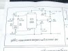
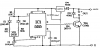
But I have a small 25watt PWM controller that works for 12v..

is it possible to use 24v?

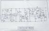
I attached 2 circuit diagrams the large diagram is the 30A motor controller,
the larger diagram top right area of the diagram is [J] this is the selection jumper for 24v.

I dont require 12/24v only 24v for the small circuit..
I will be driving a string of LEDs approx 6 or 7watts max.. thr 30A is overkill.

if you require other information about these kits.. please ask..

thanks for you help
Shaun
 

Attachments

  • P1030659..jpg
    P1030659..jpg
    381.3 KB · Views: 6,023
  • P1030657..jpg
    P1030657..jpg
    812.4 KB · Views: 2,778
You can modify the small diagram for 24V@30A.

Reduce R4 to 10R

Power the 555 timer from an LM7812.

And replace Tr1 with a suitably rated power MOSFET.
 
I do not require a Large Load

maximum is 7watts... very small loads..

I only require the small circuit to work @ 24v...

I am thinking I'd only need to change the value of 1 or 2 resistors. and by how much.. I dont know..

I hope you can help to just adjust it to work with 24v..
 
I am thinking I'd only need to change the value of 1 or 2 resistors. and by how much.. I dont know..

I hope you can help to just adjust it to work with 24v..

No, the 555 has a maximum voltage rating of 15V.

You need a voltage regulator.
 

Attachments

  • 24V 555 PWM..PNG
    24V 555 PWM..PNG
    11 KB · Views: 25,524
Last edited:
thankyou so much for your comment and your answer...

:)

I will order some 15A motor controllers they r cheaper then 30a ones...

:) bye
 
WOOOOO, I didnt see the diagram!

did you have that on file? or did u just write that?

thankyou so much

so I just put the regulator inbetween that circuit path!..

thanks again.. I will give that a shot
 
WOOOOO, I didnt see the diagram!

did you have that on file? or did u just write that?

thankyou so much

so I just put the regulator inbetween that circuit path!..

thanks again.. I will give that a shot


Is C3 a ceramic type cap?
or one of those round ones with +/--
 
WOOOOO, I didnt see the diagram!

did you have that on file? or did u just write that?
I cleaned up the fuzzy JPG you posted using the Gimp and added the voltage regulator.

Is C3 a ceramic type cap?
or one of those round ones with +/--
Yes, ceramic is fine.
 
Hello all!
For this schematic provided by the Mr Toxsick is there a made PCB​​, if there is please let him reply here.
Question: Is or can be substituted with a MOSFET P80NF5 with IRFP-054N?
thanks
 

Attachments

  • Shema-1.jpg
    Shema-1.jpg
    812.4 KB · Views: 2,939
Last edited by a moderator:
Hello
I pray for the PCB for this schematic.
If you set it here.
Thank you in advance
 

Attachments

  • Shema-1.jpg
    Shema-1.jpg
    812.4 KB · Views: 1,109
Last edited:
Status
Not open for further replies.

Latest threads

New Articles From Microcontroller Tips

Back
Top