Hello all,
new on here so please be gentle") .
.
Having problems with bought in pwm controller boards for a new product which MUST have reliable motor speed control.
Motor: 24v dc 3.3a 60w pm.(Parvalux)
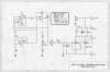
Circuit is 12+12v (24v)toroid transformer,rectifier, smoothing cap,pwm board, speed pot in hand held unit.
First board tried was Velleman K8004 which worked fine for a while then would only give full speed(I assume one of transistors failed)at 6.5a max,8-35v it was probably running close to it's limits.
Second board was US made 8-36v, 24a cont. inductive load which appears to be very well made (currently on ebay) and also worked ok for a while (tested by varying speed up/down switching on/off numerous times over a few days to simulate customer use).This also failed after a while but motor was not getting any current although meter showed 38v!!!! in circuit before pwm, with pwm disconnected meter gave 25v.
There is a diode on both boards near the output which I assume is to prevent damage to the transistors, would a second diode close to the motor brush leads be more effective or is there something blindingly obvious (once you know) that I have overlooked?
Does the smoothing cap (10000uf) need a bleed resistor, if so what value?
Would a simple rheostat generate a lot of heat, I could live with the loss of efficiency?
Would a board with a higher voltage rating solve the problem?
If anyone can shed any light on this I would greatly appreciate it as this is getting expensive.
Many thanks.
new on here so please be gentle
.Having problems with bought in pwm controller boards for a new product which MUST have reliable motor speed control.
Motor: 24v dc 3.3a 60w pm.(Parvalux)
Circuit is 12+12v (24v)toroid transformer,rectifier, smoothing cap,pwm board, speed pot in hand held unit.
First board tried was Velleman K8004 which worked fine for a while then would only give full speed(I assume one of transistors failed)at 6.5a max,8-35v it was probably running close to it's limits.
Second board was US made 8-36v, 24a cont. inductive load which appears to be very well made (currently on ebay) and also worked ok for a while (tested by varying speed up/down switching on/off numerous times over a few days to simulate customer use).This also failed after a while but motor was not getting any current although meter showed 38v!!!! in circuit before pwm, with pwm disconnected meter gave 25v.
There is a diode on both boards near the output which I assume is to prevent damage to the transistors, would a second diode close to the motor brush leads be more effective or is there something blindingly obvious (once you know) that I have overlooked?
Does the smoothing cap (10000uf) need a bleed resistor, if so what value?
Would a simple rheostat generate a lot of heat, I could live with the loss of efficiency?
Would a board with a higher voltage rating solve the problem?
If anyone can shed any light on this I would greatly appreciate it as this is getting expensive.
Many thanks.