Continue to Site

Welcome to our site!

Electro Tech is an online community (with over 170,000 members) who enjoy talking about and building electronic circuits, projects and gadgets. To participate you need to register. Registration is free. Click here to register now.

  • Welcome to our site! Electro Tech is an online community (with over 170,000 members) who enjoy talking about and building electronic circuits, projects and gadgets. To participate you need to register. Registration is free. Click here to register now.

Push button

Status
Not open for further replies.
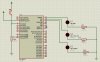
Hello guys Iam testing a button, This is how I want my project to work. When a button is pushed or pressed the three LEDs must be on.But when I push the button the LEDS do not light. can any one help me. On the attachment I have the design (proteus design) and the hex file. the code for my project is shown below
Code:
	list      p=16f877            ; list directive to define processor
	#include <p16f877.inc>        ; processor specific variable definitions

	__CONFIG _CP_OFF & _WDT_OFF & _BODEN_ON & _PWRTE_ON & _RC_OSC & _WRT_ENABLE_ON & _LVP_ON & _DEBUG_OFF & _CPD_OFF


;***** VARIABLE DEFINITIONS
w_temp        EQU     0x7E        ; variable used for context saving
status_temp   EQU     0x7F        ; variable used for context saving

;**********************************************************************
		ORG     0x000             ; processor reset vector
		clrf    PCLATH            ; ensure page bits are cleared
  		goto    Main              ; go to beginning of program


		ORG     0x004             ; interrupt vector location
		movwf   w_temp            ; save off current W register contents
		movf	STATUS,w          ; move status register into W register
		movwf	status_temp       ; save off contents of STATUS register


; isr code can go here or be located as a call subroutine elsewhere


		movf    status_temp,w     ; retrieve copy of STATUS register
		movwf	STATUS            ; restore pre-isr STATUS register contents
		swapf   w_temp,f
		swapf   w_temp,w          ; restore pre-isr W register contents
		retfie                          ; return from interrupt
Init 
        clrw                 ; Zero.
        movwf   PORTB        ; resets input/output ports
        bsf     STATUS,RP0   ; Select Bank 1
        movlw   b'00000000'  ; Set port B bits as outputs
        movwf   TRISB        ; Set TRISB register.
        bcf  STATUS,RP0      ; Select Bank 0
        retlw 0
Main
        call Init

button_pressed
         btfss PORTA,0       ;check whether button is pressed
         goto button_pressed ; if not pressed keep checking or looping
         goto loop          ; if pressed then turn on the LEDs

loop
        bsf  PORTB,0  ;turn on the red light
        bsf  PORTB,1  ;turn on the yellow light
        bsf  PORTB,2  ;turn on the green light
        goto loop
 end
 

Attachments

  • button.zip
    15.5 KB · Views: 101
  • circuit diagram.jpg
    circuit diagram.jpg
    148.1 KB · Views: 174
hi
You have the inputs of PORTA set as Analog.
 
hi
You have the inputs of PORTA set as Analog.
oh thanks, I have edited it to
Code:
	list      p=16f877            ; list directive to define processor
	#include <p16f877.inc>        ; processor specific variable definitions

	__CONFIG _CP_OFF & _WDT_OFF & _BODEN_ON & _PWRTE_ON & _RC_OSC & _WRT_ENABLE_ON & _LVP_ON & _DEBUG_OFF & _CPD_OFF


;***** VARIABLE DEFINITIONS
w_temp        EQU     0x7E        ; variable used for context saving
status_temp   EQU     0x7F        ; variable used for context saving

;**********************************************************************
		ORG     0x000             ; processor reset vector
		clrf    PCLATH            ; ensure page bits are cleared
  		goto    Main              ; go to beginning of program


		ORG     0x004             ; interrupt vector location
		movwf   w_temp            ; save off current W register contents
		movf	STATUS,w          ; move status register into W register
		movwf	status_temp       ; save off contents of STATUS register


; isr code can go here or be located as a call subroutine elsewhere


		movf    status_temp,w     ; retrieve copy of STATUS register
		movwf	STATUS            ; restore pre-isr STATUS register contents
		swapf   w_temp,f
		swapf   w_temp,w          ; restore pre-isr W register contents
		retfie                    ; return from interrupt
Init 
        clrw                         ; Zero.
        movwf   PORTB        ; resets input/output ports
        movwf   PORTA        ; resets input/output ports
        bsf     STATUS,RP0   ; Select Bank 1
        movlw   b'00000000'  ; Set port B bits as outputs
        movwf   TRISB        ; Set TRISB register.
        movlw   b'00000001'  ; set RA1 as input pin
        movwf   TRISA        ;set TRISA register
        bcf  STATUS,RP0      ; Select Bank 0
        retlw 0


Main
        call Init

button_pressed
         btfss PORTA,0          ;check whether button is pressed
         goto button_pressed ; if not pressed keep checking or looping
         goto loop              ; if pressed then turn on the LEDs

loop
        bsf  PORTB,0  ;turn on the red light
        bsf  PORTB,1  ;turn on the yellow light
        bsf  PORTB,2  ;turn on the green light
        goto loop
 end
and still it did not work
 
hi,
Look at this, it works.
Add the two line into your init

Code:
     movlw    0x07
    movwf    ADCON1

Code:
Init 
        clrw                 ; Zero.
        movwf   PORTB        ; resets input/output ports
        bsf     STATUS,RP0   ; Select Bank 1
     movlw    0x07
    movwf    ADCON1     
        movlw   b'00000000'  ; Set port B bits as outputs
        movwf   TRISB        ; Set TRISB register.
        bcf  STATUS,RP0      ; Select Bank 0
        retlw 0
 
Last edited:
Iam so happy it works. The way I know assembly is that, I had to make sure that PORTA, pin 0 is the input by initialising it
such that this instraction
Code:
btfss PORTA,0       ;check whether button is pressed
can work, So I decided to include this instractions on the initialisation
Code:
 movlw   b'00000001'  ; set RA1 as input pin
 movwf   TRISA        ;set TRISA register
I would be glad if you can tell me why it is working when using these instructions
Code:
 movlw    0x07
 movwf    ADCON1
Thank you very much
 
Last edited:
hi,
When the PIC powers up, the AN0 pins are always initialised as analog inputs, so if you want to use them as digital inputs you MUST use ADCON1 in the 16F877.
Look at the datasheet for the 16F877 in the ADCON1 section it explains the init.
 

Attachments

  • 000esp01.gif
    000esp01.gif
    4.9 KB · Views: 160
Last edited:
Thank you very much, I have even modifeid the code, now when you push/press the button the LEDs light and when you release the button the LED's light turn off.
Code:
button_pressed
         btfss PORTA,0       ;check whether button is pressed
         goto  released     ; if not pressed turn the LEDs off
         goto pressed       ; if pressed then turn on the LEDs

pressed
        bsf  PORTB,0  ;turn on the red light
        bsf  PORTB,1  ;turn on the yellow light
        bsf  PORTB,2  ;turn on the green light
        goto button_pressed

released
       bcf PORTB,0    ;turn off the red light
       bcf PORTB,1    ;turn off the yellow light
       bcf PORTB,2    ;turn off the green light
       goto button_pressed
 
Last edited:
Status
Not open for further replies.

Latest threads

New Articles From Microcontroller Tips

Back
Top