Continue to Site

Welcome to our site!

Electro Tech is an online community (with over 170,000 members) who enjoy talking about and building electronic circuits, projects and gadgets. To participate you need to register. Registration is free. Click here to register now.

  • Welcome to our site! Electro Tech is an online community (with over 170,000 members) who enjoy talking about and building electronic circuits, projects and gadgets. To participate you need to register. Registration is free. Click here to register now.

Pulse oxisensor

Status
Not open for further replies.

ProFPGA

Banned
Hi All,

I am trying to make a pulse oximeter finger probe , i have 50% success as i can get a clear heart beat from a BW34 sensor .
The problem is when i turn the IR LED off and keep RED LED on , i dont get any pulsating data ?

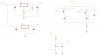
I have read many app note , where the circuit drives both LED's at +3.3V , do i have to increase the voltage for RED LED ??? any clues ??

See my circuits attached

Regards
 

Attachments

  • FingerSensor_Blockdia.jpg
    FingerSensor_Blockdia.jpg
    7.3 KB · Views: 192
  • POFrontendckt.png
    POFrontendckt.png
    12.9 KB · Views: 178
You ought to know that LED brightness is controlled by current and that shorter wavelengths have higher voltage.
usually IR =1.2V and RED=2.1V thus each requires a different Rs to 3.3 to control the current.

Your design incorrectly shared the same R thus with RED there was less voltage drop across Rs meaning less current.

Can you solve it from here?

I use RED 30 deg 10,000 mcd. For this application I think the smallest lens angle is best for maximum intensity.
 
Hi ProFPGA,

Here is a rearrangement of you circuit which is simpler and should provide an improved performance.

spec

Issue 2 of 2016_08_17
2016_08_16_!ss1_ETO_PULSE_OXIMETER.png
NOTES
(1) The value of R13 is notional and defines the red LED on current.
(2) The value of R14 is notional and defines the IR LED on current.
(3) The value of R9 is notional and defines the opto receiver diode speed and voltage gain.
(4) I would imagine that the output from the opto receiver diode would need to be amplified with an opamp.
(5) If the microcontroller operates from a 3.3V supply line, I would imagine that a potential divider will be required between the oximeter and GP103.
(6) The sense of GP104 is now reversed (high turns the red LED on).
(7) The sense of GP105 is now reversed (high turns the IR LED on).
(8) R11 is included to speed the red LED turn-off.
(9) R12 is included to speed the IR LED turn-off.
(10) C1 is ceramic X7R dielectiric, +- 10% or better, through hole (not surface mount), 18V minimum. A higher capacitance can be fitted.
(11) C1 should be mounted as close as possible to the terminals of the voltage regulator.
(12) C4 is ceramic X7R dielectiric, +- 10% or better, through hole (not surface mount), 10V minimum. A higher capacitance can be fitted.
(13) C4 should be mounted as close as possible to the terminals of the voltage regulator.
(14) C7 is aluminum dielectric, +- 20% or better, 10V minimum. A higher capacitance can be fitted.
(15) All resistors are metal film, 5% or better, 250mW minimum (unless otherwise stated).
 
Last edited:
spec Your RED LED has lower current then the IR with R13=R14

ProFPGA , you just need to compute the current you want and choose separate R's for each LED.
PNP off 3.3V is Ok or 5V, whatever you choose with different R values of course.
IR LED's have a lower Vf and also can support higher currents than the same size RED.
Choose parts for the maximum Luminous Intensity , Iv, for best results.
Pulse currents may exceed average according to specs.

Photodiode R value affects both rise time and voltage gain.

Also unless you can calibrate your Iv value emitting from each LED, you can expect as much as a 3:1 variation in batches , sometimes more. My supplier has single bin 10% tolerance.
 
Last edited:
Tony, it is the architecture of the circuit that counts at this stage. The values you mention can all be adjusted. None of us know what the characteristics of the system are at the moment because we do not know what the red LED or IR LED are. Current is not the end of the story. The same thing applies to the opto detector. Don't trouble me with details.:)

spec

Update of 2016_08_17: notes have now been added to the schematic in post #3
 
Last edited:
Oxiometers are based on ratio of absorption of O2 content in hemoglobin at two wavelengths.
Red and NIR. The absolute variation is less than the variation in any standard LED, so source selection and calibration are critical for emission levels. Since the PD is too simple to detect a wide range in levels, detecting pulse rates for both wavelengths makes these levels even more critical, unless some AGC is used for pulse detection.

Before resolving this problem , other problems are likely to exist and all or any of these may affect the solution.

Nevertheless, signal to noise ratio and absolute levels are crucial to calibration and pulse detection.

I think the OP needs help with the analog specs. for tolerances on Vcc, If, Vf , Iv, which all affect the results.
A brighter RED LED may be obvious, but how bright is my implied question and what accuracy on O2 calculations is desired can be readily defined with further details on the system.
 
Hardly worth making as they are available on Ebay for $12. Ive purchased several for people & work Ok.
 
Oxi o meter

daffynition: a round device for measuring number of queries that re-invent the wheel and is not a ohmeter to measure your resistance from buying TV ads on a high pitched white cleaning powder salesman.
 
Last edited:
your forgiven .. too many clone products spelled the incorrect way.
 
Thankyou all for insightful ideas , yes i am not RE-inventing the wheel i am trying to measure the performance of an algorithm that will also measure BP from this data .

As for the circuit design , i detected that i burned my IR LED by not putting a series Resistor , now i am testing them both with 220 ohm series resistor and using PN2222A transistor to switch them on and off alternatively from PWM source , the PWM source output is 4.58V peak pulse therefore using CD74HCT02E as a buffer . IF this arrangement still fails to output pulsating data when RED LED is on i will try "Spec" 's ckt .

Fingers crossed :)
 
spec's circuit is no better for sensitivity.

In order to get more RED sensitivity , you need to match the Luminous Intensity of the RED to the IR LED.
Please define your LED P/N , V+ and PD cct . Each LED must have a different Rs. ALso what pulse width and duty cycle?

What levels do you get?
 
LM317 burned both of my RED and IR :-(

Looking for fixed +3.3V regulator , how about LD1117 ? any circuits for getting +3.3V or as my 7805 is still working should i use a voltage divider to get +3.3 out of it .
I will buy new RED and IR LED, and see what their datasheets are suggesting , maybe this time i would burn them and also use a Zener in parallel as well ( dam Chinese parts )

I noticed that "spec" circuit has only 220 ohm resistance in series , and connected to 5V output of an 7805 , wont that also burn away the RED/IR LED's ???
 
If you use Spec's circuit, or if you drive the LEDs with low-side NPN transistors such as the 2222a, then you don't need a 3.3V regulator. If you use the circuit in post #1 then you risk frying the micro unless you include series base resistors for both transistors.

This calculator will help you choose the correct resitors to control the LED current.
 
Last edited:
LM317 burned both of my RED and IR :-(

Looking for fixed +3.3V regulator , how about LD1117 ? any circuits for getting +3.3V or as my 7805 is still working should i use a voltage divider to get +3.3 out of it .
I will buy new RED and IR LED, and see what their datasheets are suggesting , maybe this time i would burn them and also use a Zener in parallel as well ( dam Chinese parts )

I noticed that "spec" circuit has only 220 ohm resistance in series , and connected to 5V output of an 7805 , wont that also burn away the RED/IR LED's ???
This can be made to work on any voltage from 3.3V to say 12V
You compute the voltage drop on the series R for each diode to choose the current needed like 10mA.
so for IR Vf=1.2 and Red Vf=2.1. using Vcc=5V, and allow Vce drop=0.1
Rir= 3 7V/10mA =370 Ω +\- 10%
Rred=2.8V/10mA=280 Ω. +\- 10%
Then I base=~10% of load or (5V-0.7)/1mA = 4k3

basic Ohm's Law
 
Last edited:
LM317 burned both of my RED and IR :-(

Looking for fixed +3.3V regulator , how about LD1117 ? any circuits for getting +3.3V or as my 7805 is still working should i use a voltage divider to get +3.3 out of it .
I will buy new RED and IR LED, and see what their datasheets are suggesting , maybe this time i would burn them and also use a Zener in parallel as well ( dam Chinese parts )

I noticed that "spec" circuit has only 220 ohm resistance in series , and connected to 5V output of an 7805 , wont that also burn away the RED/IR LED's ???

Don't mess about. My circuit will not only protect the LEDs but it is simpler, more reliable, more predictable and more suitable for development and optimization.

3.3V is not really suitable for driving LEDs unless you use a constant current source, but even then it would not drive all LEDSs, some of which have a forward drop over 3.3V.

You are misreading LED requirements: LEDs should be driven with a current source not a voltage source. That is why you are blowing your LEDs.

Don't listen to Tony he stating all sorts of random information without quantifying any of it, or keeping it in context- as usual.:p

spec
 
haha spec at least I know how to compute LED current and all the variables that will affect his "algorithm" like luminous intensity, , If and beam width. But the components selected or "specs" are a big unknown. You can't compute O2 with wide tolerances, unless you do ratiometric PD calibration with a diffuser and without a finger.
 
Last edited:
Status
Not open for further replies.

Latest threads

New Articles From Microcontroller Tips

Back
Top