Electro Tech is an online community (with over 170,000 members) who enjoy talking about and building electronic circuits, projects and gadgets. To participate you need to register. Registration is free. Click here to register now.
Welcome to our site! Electro Tech is an online community (with over 170,000 members) who enjoy talking about and building electronic circuits, projects and gadgets. To participate you need to register. Registration is free. Click here to register now.
I need a circuit detecting pulse duration; when the pulse duration exceeds about 5 seconds (adjustable), the output needs to get high and stay high for the duration of the pulse + a hysteresis of about 5 seconds too (adjustable too).
You mean like "ATtiny85"? Or Atmega328 or similar. There will be a ESP8266 involved in the circuit where this needs to be included (this controller can be used with Atmega328 compiler).
Yes, go ahead..
But if possible a simple hardware solution would be preferred because the adjustments if needed can be done by a trimpot.
Hi dknguyen, I know that can be done. But my prefered solution would be a hardware solution if possible: the ESP8266 does not have an accurate ADC and I do rather not include one more controller just for this. Would this not be possible with a 555 or other simple hardware?
Hi dknguyen, I know that can be done. But my prefered solution would be a hardware solution if possible: the ESP8266 does not have an accurate ADC and I do rather not include one more controller just for this. Would this not be possible with a 555 or other simple hardware?
Just google '555 missing pulse detector', it's a VERY standard circuit.
However, as you've got an ESP8266 that it's going to connect to, why not just do it in software? - and (as already suggested) use the ADC fed from a pot for a manual adjustment, the ADC is FAR more accurate than anything you need, and even more so as the pot will be fed from the same voltage reference, thus cancelling out any errors there.
However, having just read your OP, you want BOTH to be adjustable, and there's only one ADC on an ESP8266 - but it's trivial to connect a capacitor and pot to a pin and measure the pots value by measuring how long the cap takes to charge or discharge (there's a PIC example in my tutorials, and it was also the way PC joystick ports worked).
The signal triggers a 5 s timer (adjustable). The end of that period triggers another timer that adds 5 s (adjustable) to however long the original signal stays high.
The signal triggers a 5 s timer (adjustable). The end of that period triggers another timer that adds 5 s (adjustable) to however long the original signal stays high.
Now it is 2 to 2 for analog vs digital solution. I will try and come up with AnalogKid solution version; and meanwhile investigate dkngyen/Nigel Goodwin proposal.
Since I already use 555's for my circuit I will try to get something going on that (analog) path first.
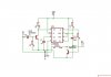
Below is the LTspice simulation of a circuit, to do the pulse detection and stretching.
This is the simplest analog circuit I could generate.
I first tried using 555's but that became even more complicated.
This circuit uses one LM339 comparator chip, one CD4013 flip-flop, two diodes, and some passive components.
The two LM339's, U1 & U2, are configured to provide about a 5 second delay each.
U4 is configured as an input buffer.
The simulation is shown for an input pulse of >5s.
≈5s after the input pulse V(input) goes high, U1 Out goes high.
This triggers the flip-flop, U3, causing its Q Output to go high.
At the end of the input pulse, U2 starts to time, and after ≈5s its output, Out2 goes high, resetting the flip-flop and terminating the Output.
The circuit thus gives an output pulse that starts when the input pulse exceeds the 5s delay, and continues the output pulse until 5s after the end of the input pulse (hysteresis?), which I think is what you wanted.
These periods can be adjusted by pots U6 and U7.
So you have to decide between the complexity of this circuit and a simpler micro circuit.
I wouldn't worry about the accuracy of the A/D in the micro, since it's just reading a pot.
It's stability you want, and the micro's A/D should be quite stable.
Amazing! Thank you for your work!! I will try that out on a breadboard.
While you were doing all this hard work I did some Googling and came across an obscure detector that uses a 555: it gives a high output when the incoming pulse is longer than the monostable time set on a 555. It does not take into account the second requirement (5s delay after end of input pulse).
What do you think of that circuit?
This site uses cookies to help personalise content, tailor your experience and to keep you logged in if you register.
By continuing to use this site, you are consenting to our use of cookies.