Continue to Site

Welcome to our site!

Electro Tech is an online community (with over 170,000 members) who enjoy talking about and building electronic circuits, projects and gadgets. To participate you need to register. Registration is free. Click here to register now.

  • Welcome to our site! Electro Tech is an online community (with over 170,000 members) who enjoy talking about and building electronic circuits, projects and gadgets. To participate you need to register. Registration is free. Click here to register now.

Puls with 40106

Status
Not open for further replies.

voxac30

New Member
Hi!
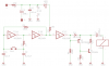
I m new here and more analog -Tube guy .I build also guitar stompboxes .I have build a existed shematic to turn on -off a bistable mini relay with momentary button . Schematic 1 works fine .A 40106 was used -3 gates are unused .My problem is -I want to use optofet TLP 222 from Toshiba to mute Audio signal in the time during relay switch .This was realized with microcontrolers on others projects but i will use unused gates of 40106 . I need short puls when momentary button is pressed for about 30-40ms for audio muting to turn on led in optofet .I have build second schematic -wired after second gate of the first schematic ,but diode turn on every second cycle -turn on momentary switch.? I need reset function -when i touch push button -short puls 30-40ms ,another touch second pulse ..? Voltage used is 9v.
Thanks for help
gsb
 

Attachments

  • OPTO FET.png
    OPTO FET.png
    890 bytes · Views: 195
  • Relay Switching.png
    Relay Switching.png
    11.5 KB · Views: 168
  • pulse.gif
    pulse.gif
    6.8 KB · Views: 376
Last edited:
The reason you only get a pulse on every other button press is that your pulse circuit only works on the high to low transition at pin 6 of the 40106 You also need a pulse for the low to high transition. If you separate the two inputs on your pulse generator circuit and have a C/R delay on both you can have one capacitor connected to pin 6 as it is at present and the other capacitor fed from an inverted version of the signal which is available at pin 4 or 5 of the 40106. I think this will now do what you want.

Les.
 
Welcome mr guitar amp.
I agree with Les on this one, a edge triggered monostable is what you need.
I have repaired a few Ac30's, you dont see many these days with the original bulldog speakers.
 
1. Delete R4. Pin 6 is always either high or low, so the base never is left floating.
2. Add a resistor in series from Q2 base to pin 6.
3. Is the block to the right (P$1, P$6) the main audio switching relay or the new opto relay you want to add?
4. What is the intent of the D1 and C3?

The basic problem is that you have an alternate-action signal and you want to trigger one circuit from both the high and low edges. The "pulse" schematic fires on negative edges only. Not a big problem, this can be done with the remaining 3 gates in the 40106.

ak
 
It looks like, in the circuit with three 40106, will change state with every push of the button.
You want a pulse every button push.
upload_2016-12-9_11-32-11.png
 
Hi
Thanks for help. How to separate inputs on pulse circuit ? Cr combination from 4 and another from 6 on input from pulse circuit 9 . If I understand both CR on one input . Diode must have positiv puls to light up.Answer to Analog Kid
3- that is existing circuit to fire bistable relay ,C3 give a quick charge and fire relay when button ist pressed .Power consumption is low ,relay is energized only when button is pressed .Optofet will be aded on audio part to pull signal to ground an make mute for short time .
gsb
 
This is how to seperate the two inputs of your two input NAND gate.
Double pulse.jpg

It may be easier to understand if you think of it as a two input OR gate with active low inputs and an active high output. Taking either (or both inputs low) makes the output go high. The top input is connected as before and this will generate a pulse when pin 6 goes from high to low. You also need a pulse when it goes from low to high. The ignal on pin 5 is the inverse of the signal on pin 6 so when pin 6 goes high pin 5 will go low which will generate a negative pulse on the lower input. so you will now get a pulse at the output on both transistions. which I think is what you require to mute the audio path just as the latching relay switches in either direction.

Les.
 
The problem with Ron's circuit in post #5 is that it requires one end of the switch to be tied to Vcc (or GND in another variation). But a limiting characteristic of the dual-inverter toggle flipflop is that neither end of the switch can connect to a rail. So only the two outputs (pins 2 and 4) are what is available to drive a pulse former. Les's circuit in post #7 captures the requirement, but the task is to do it with three inverters and no other gates. Scrambling with house stuff, I'll try to get a schematic up later today. Hint: with two diodes it takes only one inverter for the combiner.

ak
 
I don't understand the significance of your statement "
I have only 1 diode ( in optofet ) .
gsb
My understanding was that the pulse that is generated in your circuit Pulse.gif and the modified version I described in post # 2 and then drew in post # 7 is required to occurr on every transition of the latching relay. This pulse then drives the LED side of the opfet. (Either directly or via a transistor.) The Fet side (output side) then mutes the audio. Am I correct ?

Les.
 
BTW - unless there is an explicit reason to use a mechanical relay to switch the audio, Maxim, Linear Tech, and National (now TI) all make analog switches designed specifically to eliminate pots at the switch point. Some have controlled rate of change, and some have zero-crossing detectors.

ak
 
Hi !
I will try to build post #7 how it works , from Les Jones -yes thats corect i have write nonses . Yes Led side of optofet will be drived directly with resistor .I have good experience with relays in my builds so i will leave them .
I have use years ago some IC,s from Analog Devices SSM2404 analog Switch for preamp source switching .Excelent performance ,I think they are obsolet now.
gsb
 
Hi!
Thanks Les Jones ,a have fixed my problem. One CR on 4 one on 5 then on two gates an outputs together on diode .One gate is left free ,but it works like charm. Thanks one more time.
voxac30
 
Status
Not open for further replies.

Latest threads

New Articles From Microcontroller Tips

Back
Top