Hi,
I want to turn an old(er) 300w ATX PSU into a bench supply for my electronics. I've probed it and it seems to follow the ATX pinout, and voltages seem pretty accurate.
I've created a circuit with an LCD and PICAXE, along with 2 LEDs and 3 Switches. This will allow me to turn on/off the PSU and various other info maybe in the future.
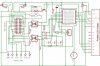
Attached is an eagle schematic picture. It works like this:
The molex input on the left is for the main power connector on the PSU (20 pins). The 6 pins at the bottom left are the screw terminals (large 6mm coloured things) for the output. This allows me GND, +12v, +5v, -5v, -12v and 3.33v. I actually have another board which has the terminals mounted on it which has seperate GND and Voltage for each set of voltages plus a +7v connection (12v and 5v = 7v). This means there are a total of 12 actual screw terminals.
The PSU is started when the Pin 14 is connected to ground through the relay - this is fired from a transistor from a PICAXE output. This would be coded into so it would turn on/off when you press S1 (the first switch). The LCD would show that it is on. There are 2 LEDs top-left, one showing its in standby and one showing that it is on.
There are 2 optoisolators which are triggered by the +12v and +5v line. This allows the picaxe to monitor if the 12 and 5 lines are working ok and will display this on the LCD.
The two resistors and 3 pin connection just under the PICAXE is the download circuit for updating the firmware.
There is also a piezo for alerts or beeping and pot for contrast adjustment.
I hope one of you can just check that it looks ok and the circuit looks safe to connect up. I will be getting the PCB manufactured by a friend with access to a CNC machione for PCBs next week so needs to be confirmed by then.
Thanks,
computer
Note: I have just realised that the diode protection for the relay is backwards - I've fixed this in eagle now but not the JPG I've attached!
I want to turn an old(er) 300w ATX PSU into a bench supply for my electronics. I've probed it and it seems to follow the ATX pinout, and voltages seem pretty accurate.
I've created a circuit with an LCD and PICAXE, along with 2 LEDs and 3 Switches. This will allow me to turn on/off the PSU and various other info maybe in the future.
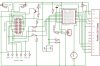
Attached is an eagle schematic picture. It works like this:
The molex input on the left is for the main power connector on the PSU (20 pins). The 6 pins at the bottom left are the screw terminals (large 6mm coloured things) for the output. This allows me GND, +12v, +5v, -5v, -12v and 3.33v. I actually have another board which has the terminals mounted on it which has seperate GND and Voltage for each set of voltages plus a +7v connection (12v and 5v = 7v). This means there are a total of 12 actual screw terminals.
The PSU is started when the Pin 14 is connected to ground through the relay - this is fired from a transistor from a PICAXE output. This would be coded into so it would turn on/off when you press S1 (the first switch). The LCD would show that it is on. There are 2 LEDs top-left, one showing its in standby and one showing that it is on.
There are 2 optoisolators which are triggered by the +12v and +5v line. This allows the picaxe to monitor if the 12 and 5 lines are working ok and will display this on the LCD.
The two resistors and 3 pin connection just under the PICAXE is the download circuit for updating the firmware.
There is also a piezo for alerts or beeping and pot for contrast adjustment.
I hope one of you can just check that it looks ok and the circuit looks safe to connect up. I will be getting the PCB manufactured by a friend with access to a CNC machione for PCBs next week so needs to be confirmed by then.
Thanks,
computer
Note: I have just realised that the diode protection for the relay is backwards - I've fixed this in eagle now but not the JPG I've attached!