Continue to Site

Welcome to our site!

Electro Tech is an online community (with over 170,000 members) who enjoy talking about and building electronic circuits, projects and gadgets. To participate you need to register. Registration is free. Click here to register now.

  • Welcome to our site! Electro Tech is an online community (with over 170,000 members) who enjoy talking about and building electronic circuits, projects and gadgets. To participate you need to register. Registration is free. Click here to register now.

Proteus Atmega328P not working at 16MHz clock frequency

Status
Not open for further replies.

SupunDK

New Member
Hey all,

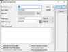
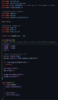
I want to run the Atmega328P at 16MHz. I have configured the timer 2 overflow interrupt to run at 8 kHz considering the AVR runs at a 16 MHz frequency (shown in a picture below). But when I checked the time between two successive timer interrupts, it shows that it runs at 4 kHz frequency. I have also attached a photo of the fuse settings.

I would really appreciate it if someone could help me with this problem.

Fuse settings.png
 

Attachments

  • crystal settings.png
    crystal settings.png
    16.2 KB · Views: 520
  • code_1.png
    code_1.png
    92.5 KB · Views: 387
  • timer_overflow_interrupt.png
    timer_overflow_interrupt.png
    8.8 KB · Views: 334
  • timer_settings.png
    timer_settings.png
    56.2 KB · Views: 373
I'm not familiar with AVR, but with PICs the internal clock (peripheral clock) is half the main clock.

Could that be the same?
 
According to the datasheet... The CLKDIV8 is on by default... 16Mhz clock -> 2Mhz system clock..

Remember.. The clock on the proteus model is not simulated.. If you put 16Mhz then thats is your speed..Unless you have the internal 8Mhz selected in the fuses, then Proteus defaults to that..
 
Not familiar with the ATMEGA hardware but if you set the clock to rollover at 8kHz and you toggle an output on each rollover then it will output 4kHz. The changes will happen at 8kHz, but two changes are needed to make 1 wave.

Mike.
 
According to the datasheet... The CLKDIV8 is on by default... 16Mhz clock -> 2Mhz system clock..

Remember.. The clock on the proteus model is not simulated.. If you put 16Mhz then thats is your speed..Unless you have the internal 8Mhz selected in the fuses, then Proteus defaults to that..
Thank you for the reply.

Here I have unprogrammed the CLKDIV8 fuse and I have set the CKSEL fuses to (0111) External Full Swing Crystal. The clock frequency is also set as 16 MHz (external 16 MHz crystal is also connected). Doesn't that ensure that the Atmega chip is running at 16MHz?
 
I'm not familiar with AVR, but with PICs the internal clock (peripheral clock) is half the main clock.

Could that be the same?
Thank you for the reply.

Here I have set the CLKDIV8 fuse to 1 and CLKPR register to 0x00. I think that ensures that the system clock and the peripheral clock is the same frequency.
 
Just realised you're using an Arduino, I did similar to generate a 38kHz output for infrared. This is the code I used,
Code:
  // set up Timer 2
  TCCR2A = _BV (COM2A0) | _BV(WGM21);  // CTC, toggle OC2A on Compare Match
  TCCR2B = _BV (CS20);   // No prescaler
  OCR2A =  207;          // compare A register value (210 * clock speed)
                        //  = 13.125 nS , so frequency is 1 / (2 * 13.125) = 38095
I gated it on/off by setting the pin to output(on) or input(off). It's pin 11 on a Nano.

Mike.
 
Not familiar with the ATMEGA hardware but if you set the clock to rollover at 8kHz and you toggle an output on each rollover then it will output 4kHz. The changes will happen at 8kHz, but two changes are needed to make 1 wave.

Mike.
Thank you for the reply.

But here the problem that I am experiencing is that the time difference between two successive toggles is around 255 us. That translates to approximately 4 kHz. So here even though I have set the timer to roll over at 8 kHz, in the simulation it's rolling over at 4 kHz.
 
If you toggle every 250uS then that's 4000 toggles per second which is 2kHz!!! Or did I misread that?

Mike.
Edit, have you tried "rubber ducking" your code? That is, explain how it works to anything, a rubber duck, coffee cup etc. Often when you do this you realise where your mistake is.
 
Just realised you're using an Arduino, I did similar to generate a 38kHz output for infrared. This is the code I used,
Code:
  // set up Timer 2
  TCCR2A = _BV (COM2A0) | _BV(WGM21);  // CTC, toggle OC2A on Compare Match
  TCCR2B = _BV (CS20);   // No prescaler
  OCR2A =  207;          // compare A register value (210 * clock speed)
                        //  = 13.125 nS , so frequency is 1 / (2 * 13.125) = 38095
I gated it on/off by setting the pin to output(on) or input(off). It's pin 11 on a Nano.

Mike.
Thank you for this. I will compare this with my code and see.
 
If you toggle every 250uS then that's 4000 toggles per second which is 2kHz!!! Or did I misread that?

Mike.
Edit, have you tried "rubber ducking" your code? That is, explain how it works to anything, a rubber duck, coffee cup etc. Often when you do this you realise where your mistake is.
Yeah, you are absolutely correct. But here I am trying to sample an input signal when the timer overflows. So, I want to achieve a sampling rate of 8 kHz but because of the above-mentioned problem, I'm getting a 4 kHz sampling frequency.

I will also try the "rubber ducking" method to debug the code. Thank you.
 
You've programed a serial Interface too.
Does the Speed fit to 9600 ?
When Yes the Clock would work proper.

The Bug must be at an other Place.

Is there another Interupt Routine that takes a lot of time?
( Interrups should always be as short as possible )

The Timer has only one Overflow Interrupt Flag.
When the Intrrupt Handling is blocked by CLI(); or an other active Interrupt while the next Timer Interrupt occours, it only will be processed once.
So it seems to be it work to slow.
 
Status
Not open for further replies.

Latest threads

New Articles From Microcontroller Tips

Back
Top