Continue to Site

Welcome to our site!

Electro Tech is an online community (with over 170,000 members) who enjoy talking about and building electronic circuits, projects and gadgets. To participate you need to register. Registration is free. Click here to register now.

  • Welcome to our site! Electro Tech is an online community (with over 170,000 members) who enjoy talking about and building electronic circuits, projects and gadgets. To participate you need to register. Registration is free. Click here to register now.

project on bread board ?

Status
Not open for further replies.
That's what your schematic suggests and it's less destructive when an adapter is connected backwards.
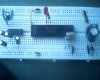
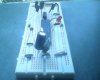
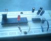
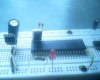
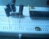
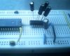
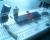
thanks sir , can you tell me that my capacitor connection is correct or not , If this is correct then I want to add db9 male connector look at post #10 I just want to confirm
 
The cap looks OK.

For good design practice a small cap like a 0.1 uf ceramic should be placed near the output of the regulator. They should also be placed next to every IC at the power pins. These are called bypass capacitors. What I gave you is a "rule of thumb". There is an art to bypassing like everything else.
 
I have replaced capacitor and few things
don't confused about led I have used Led with series resistor
I don't have usb to serial adopter so I used two cable
Db9 male connector +db9female connector------cable-----db9 female+db9male+usb port to laptop port
look this images
 

Attachments

  • IMG_0039.JPG
    IMG_0039.JPG
    52 KB · Views: 151
  • IMG_0040.JPG
    IMG_0040.JPG
    102.7 KB · Views: 154
  • IMG_0041.JPG
    IMG_0041.JPG
    113.7 KB · Views: 146
  • IMG_0042.JPG
    IMG_0042.JPG
    71.7 KB · Views: 146
Yikes!

Turn your LED 90 or 180 degrees and place it physically between the processor and the regulator. Think of it as another component. Now you can use a jumper to from the LED to +5 and a jumper from the (-) side of the LED to the port. This assumes the port sinks (connects to ground) current.

Assuming the port SINKS current. I remember 18 mA, but not sure of the source sink spec.
ok and what about other component , Is it correct? this cable will be work ?
 
"other component" - language problem. The LED is placed on the breadboard where you cannot connect to it properly, so move it physically between the processor and regulator where there is some free breadboard room. Now wire it. It HAS to have a resistor in series with the LED. Once you have that, then connect the resulting "device" (LED+Resistor) to the port and +5.

USB to serial port cables usually work, but getting serial to work in general may take some effort.

Remember that I'm looking for gross errors and not every detail.
 
"

Remember that I'm looking for gross errors and not every detail.
ok its lot for me
look max2s232 Ic, look at pin 2 and pin 16, is it correct?
and also look at led connection
 

Attachments

  • IMG_0044.JPG
    IMG_0044.JPG
    112.6 KB · Views: 151
  • IMG_0045.JPG
    IMG_0045.JPG
    111.1 KB · Views: 152
  • IMG_0046.JPG
    IMG_0046.JPG
    124.1 KB · Views: 144
You still don't seem to realize that the two rails at the top and bottom of the breadboard are continuous.

As you have linked the two together, you have your input and output of the voltage regulator on the same rail..

The LED is now connected without the resistor as the resistor is in parallel to the 5v rail, and your diode is the wrong way round.... I have done your circuit in "fritzing" so I will post it a soon as I get to work!! What ever you do... Don't connect up the power to the board.
ok look at this
 

Attachments

  • IMG_0047.JPG
    IMG_0047.JPG
    120 KB · Views: 139
  • IMG_0048.JPG
    IMG_0048.JPG
    100.8 KB · Views: 155
The LED will not light now as it is in parallel with the 5v as soon as you apply a 0v on that pin it will fry!!!
Vead.png
One last thing..... If you check out the picture.. Look at the power rail connections...

I had my LED on Po.0 but it makes no difference..
 
The LED will not light now as it is in parallel with the 5v as soon as you apply a 0v on that pin it will fry!!!
View attachment 85898
One last thing..... If you check out the picture.. Look at the power rail connections...

I had my LED on Po.0 but it makes no difference..
thank you very much Ian sir for this help
I tried but I got error message ,can you send me link where i can download Fritzing"
 
Last edited by a moderator:
Status
Not open for further replies.

Latest threads

New Articles From Microcontroller Tips

Back
Top