Continue to Site

Welcome to our site!

Electro Tech is an online community (with over 170,000 members) who enjoy talking about and building electronic circuits, projects and gadgets. To participate you need to register. Registration is free. Click here to register now.

  • Welcome to our site! Electro Tech is an online community (with over 170,000 members) who enjoy talking about and building electronic circuits, projects and gadgets. To participate you need to register. Registration is free. Click here to register now.

project on bread board ?

Status
Not open for further replies.

Parth86

Member
I need help, I am beginner , I want to learn something by doing some work on hardware I bought some electronics lab tools and component

small project - I want to blink Led using microcontroller

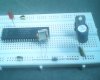
microcontroller -p89v51rd2
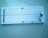
breadboard
wires black, yellow
battery 9 v dc
Electrolytic Capacitors 1000 μF
diode 1n4007
Ceramic Capacitors 22 ρf
7805 regulator
LED
crystal oscillator

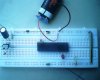
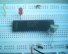
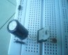
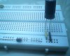
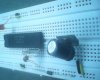
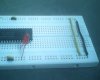
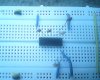
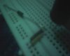
I have made some connection on breadboard, not all but trying to complete I have upload Images please check out me and tell me where i am wrong. remember this is my first project on breadboard
 

Attachments

  • IMG_0004.JPG
    IMG_0004.JPG
    139.9 KB · Views: 211
  • IMG_0007.JPG
    IMG_0007.JPG
    123.2 KB · Views: 198
  • IMG_0011.JPG
    IMG_0011.JPG
    105.5 KB · Views: 200
1. Make or buy a 5 V power supply. The 5 V regulator should have a heat sink for the short circuit protection to work. I really would not breadboard that part of the circuit. If the part gets warm, the breadboard could melt in that area. I'd solder the power supply on a PCB and add a LED "pilot light".
I would also add protection diodes. I'd put a reverse biased diode on the input and also fuse the input, so if power is connected backwards, you don't let out the "magic smoke". The fuse blows instead. Also put a reverse biased diode between Vin and Vout. This makes sure that any backfeeds go around the regulator.

Something like https://www.sparkfun.com/products/10804 this would absolutely be ideal. It plugs into the breadboard.

The breadboard area around your "power supply", you have wires going nowhere.

Do the power supply right.

==

Spending almost zero time, the LED that you have is effectively shorted out and therefore useless. I don;t know what the specs of the ports on that chip is, but you need to make sure it can source or sink about 10-20 mA and size the pull-up or pull-down resistor appropriately.
R<= (Vdd-Vf-Vs)/Iled

where Vdd is the power supply voltage. Vf is the LED forward voltage (varies by color) and Vs would be Vc-e(sat) for a bipolar transistor. It's basically the voltage loss when the transistor or FET is fully turned on. I led is the operating current in AMPs.

--

The breadboard capacitance COULD affect the ability for the oscillator to work. Not saying that it will, but it is a potential problem.
 
sorry for double post but I don't know to delete post
 

Attachments

  • IMG_0012.JPG
    IMG_0012.JPG
    49.3 KB · Views: 173
  • IMG_0013.JPG
    IMG_0013.JPG
    106.7 KB · Views: 162
I will implement circuit on pcb later First I want to check out that my circuit is working properly or not , so first i am using breadboard

check out connection for capacitor and diode
black wire - ground
yellow wire - 9v dc
 
You might find this **broken link removed** post useful.

I THINK the yellow wire is connected to the (-) side of the cap.
I can't tell where the diode band is.

The diode is useless where you have it connected.
Breadboards like you have have generally two configurations.
1) Requires the jumpers you have placed horizontally.
2) Does not require the jumpers.

The edge top and bottom rows are ALL connected together and may or may not be in 8 (like you wired it) or 4 busses.

e.g.

1111111111111 22222222222222
333333333333 44444444444444

middle

555555555555 66666666666666
777777777777 88888888888888

Not to scale and it's shown as 8 busses. Some breadboards only have 4.

If you take an ohmmeter and place it across your diode, you will find it shorted in both directions.
The diode mode will also work. It will show 0 volts and beep.
 
Last edited:
You have your crystal capacitors connected to the red wire of the battery, they should connect to the black one.
 
black wire - ground
yellow wire - 9v d

check out this images
 

Attachments

  • IMG_0018.JPG
    IMG_0018.JPG
    117.5 KB · Views: 177
  • IMG_0019.JPG
    IMG_0019.JPG
    108.2 KB · Views: 190
  • IMG_0021.JPG
    IMG_0021.JPG
    95.5 KB · Views: 179
look at this Images for capacitor connection with max rs232 Ic
yellow - 5v dc
black - ground
 

Attachments

  • IMG_0030.JPG
    IMG_0030.JPG
    135.2 KB · Views: 166
Last edited by a moderator:
TheRS232 seems to be... But your power supply isn't...

You are using the same chip as I have done in the tutorials..
which tutorial are you talking , do you mean 8051 in electro tech forum

I made power supply with microcontroller look at post #7
and now I want to add max rs232 chip on board so I made capacitor connection . I just want to confirm that connection is correct or not
 
Do what I said earlier. Take a multimeter and use either ohms or the diode scale and measure the diode in both directions in and out of circuit.

The breadboard is shorting out the diode. All of the 4 rows of pins in the horizontal direction at the edge are connected together because of your 4 jumpers, so the diode does nothing. The diode has to use one of the vertical tie-points.
 
I have taken reading in both direction its 2.0 ohms and 1.7 ohms

now i have connected positive terminal of diode to yellow wires and negative terminal with black wire that is negative

i have upload Image and sorry for bad quality of picture
 

Attachments

  • IMG_0031.JPG
    IMG_0031.JPG
    52.5 KB · Views: 177
  • IMG_0033.JPG
    IMG_0033.JPG
    53.3 KB · Views: 184
If those diode readings were out of circuit, the diode is bad.

Per your schematic, the diode is supposed to be in series. You have it in parallel.

I have a hard time seeing the diode band, so I cannot comment on the direction.

You CAN build/troubleshoot independently:
1. The power supply
2. The MAX232 chip (just loop it back) + the power supply
3) Everything
that means i need to connect in series

I understood the one end of diode should be connected to 5v yellow wire and other end should be connected to the positive end of capacitor
 
Last edited by a moderator:
Status
Not open for further replies.

Latest threads

New Articles From Microcontroller Tips

Back
Top