Continue to Site

Welcome to our site!

Electro Tech is an online community (with over 170,000 members) who enjoy talking about and building electronic circuits, projects and gadgets. To participate you need to register. Registration is free. Click here to register now.

  • Welcome to our site! Electro Tech is an online community (with over 170,000 members) who enjoy talking about and building electronic circuits, projects and gadgets. To participate you need to register. Registration is free. Click here to register now.

project (incubator control systems) update

Status
Not open for further replies.

ghostman11

Well-Known Member
hi all i thought i would post a update on how my main project is going.... a quick recap.
the project is to fully automate comercial type incubators and although them to be indevidualy setup with different paramaters depending on A. what species there incubating and B. whether the unit is being used to incubate or hatch eggs.
For the prototypes i have set up 2 test units (1. incubator 2. hatcher). theese units physicaly look nothing like the incubator units that will be used but have the same parameters such as insulation proterties etc as the final units. the main difference is size, the test units hold approx 250-350 eggs each while the finished comercial units will hold approx 600-800 eggs each.
at present the heating is supplied by way of light bulbs (2x100W with 2x100W as backup), theese will be replaced with a heating element or cable once the tempreture control unit is complete.
the eggs are on "racks" in 5 layers, the warm air is distributed to each layer via 3 rows of 3 fans each (9 in total). currently the heating and tempreture control is being handled by a comercial 4 channel unit using DS18s20 sensors (K190unit), this unit is controlled via rs232 to a pc and software written for the K190. three of the four tempreture channels also control each row of fans (On & Off).
the main fan control is via a fan control unit wich consists of a 28 pin pic (18f2585), this unit uses software pwm to vary the speed of each individualy fan in a variable pattern (currently set by a include file). the unit works well and alows fine tuning of heating rates and humidity. future development of this unit will include linking it to humidity measurment and having the fan speed and pattern altered according to tempreture and humidity.
note. the software for the fan control unit hasnt been written by me so i will not be posting the code (sorry)

Watch Dog Unit

This unit is currently based on a 40 pin pic (18f4685) and is in prototype phase so the chip may well change, the units main functions are.

1. to monitor light output from the heating bulbs and to switch in a back up bulb when a main heating bulb fails (this happens approx 3 times over a 3 week period!), this is achieved by using a LDR on each of the bulbs, when the light level drops the unit checks the k190 heating unit to see if the heater is meant to be on or off, if it is in a off condition then no action is taken, however if the k190 returns a on condition and no light output is detected then the unit switches in a back up bulb.

2. monitors the pc status,
we have frequent small powerouts (<5mins) and sometimes the pc dosnt restart properly or dosnt restart at all wich renders the k190 useless, so the WDU monitors the pc power and parralell port if the power is on but the port isnt providing signal pulses it will restrt the pc, or if the pc is off it will restrt it.

3. the unit also monitors the power supplies for the pics and the the relays etc if any of theese supplies fail it alarms and switches in a back up.

4 the unit is also connected to a LCD wich displays each the different systems status and any fault conditions that exist.

this unit is working very well as a protype unit but is currently having a a few redesign features added and the software is undergoing a exstensive rewrite, main points regarding software for this unit is i am going to add a menu system and self test function i will also add a RTC and usart function so i can log the data via RS232 on the pc.

Humidity unit

this is the newest unit i am working on and is currently in BB prototype phase.
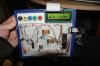
Like most of the units i use it has started life on a 40 pin pic (18f4685) but will eventualy be moved to eigther a 18 pin chip (18f1330) or a 28 pin chip (18f2685). for the senors i am using sensiron SHT71 sensors, theese measure bith tempreture and humidity although its mainly the humidity reading from them that i am interested in. i have yet to decide wether i will be using 1 or 3-4 sensors per incubator (or hatcher). currently i have a BB set up that monitors 1 sensor. the origanal driver i wrote was working fairly well but i have found a better driver that was written for a different compiler and have converted it to work with C18, i have also added usart so the tempreture, humidity and Dew Point are output to the pc for logging, i have also added a LCD where the tempreture and humidity are displayed, presently i am rewriting the software so it will monitor,display and log data from 3 sensors, the end aim at this point will be to have the unit adjust both humidity levels via a water resivouir systems and to alter the main fan unit speed and pattern according to layer humidity readings. it will also control dry air input fans and stale air exhaust fans via hardware pwm. i have included a photo of the early bread board version of the humdity sensor, ignore the messy board and the fact there is etc components not being used on the board, like i said it was a very early protype!!
anyway i hope you enjoyed the update! the next one will include some software as soon as i have tiedied it up a little!!
 

Attachments

  • humidity unit.JPG
    humidity unit.JPG
    3.2 MB · Views: 1,919
if anyone is interested i have posted some code to read 1 shtx sensor and display onto a lcd, it is a very basic version being the first code i tried and adapted fot the sht71. the code i am now doing has usart and 3 sensors with a few other things thrown in but isnt finished, also it its VERY large! if anyone whats a look i will post when it is completed.

LCD.h
Code:
 #include <delays.h>    /* for delay routines */
#include <p18cxxx.h>   /* for TRISB and PORTB declarations */ 


#define	LCD_RS		PORTDbits.RD0		// Register select
#define	LCD_EN		PORTDbits.RD1		// Enable
#define	LCD_D4		PORTDbits.RD4		// LCD data 4
#define	LCD_D5		PORTDbits.RD5		// LCD data 5
#define	LCD_D6		PORTDbits.RD6		// LCD data 6
#define	LCD_D7		PORTDbits.RD7		// LCD data 7


#define LCD_ROWS	2	// valid numbers are: 1,2
				// (set to 2 for 2 or more rows)
#define LCD_COLS	16	// valid numbers are: 8,16,20


#define LCD_CLR			0x01 // Clear Display
#define LCD_HOME		0x02 // Cursor to Home position

/************************************************************************/
#if (LCD_COLS==20)
	#define LCD_line1	0x80 // Line 1 position 1
	#define LCD_line2	0xC0 // Line 2 position 1
	#define LCD_line3	0x94 // Line 3 position 1 (20 char LCD)
	#define LCD_line4	0xD4 // Line 4 position 1 (20 char LCD)
#else
	#define LCD_line1	0x80 // Line 1 position 1
	#define LCD_line2	0xC0 // Line 2 position 1
	#define LCD_line3	0x90 // Line 3 position 1 (16 char LCD)
	#define LCD_line4	0xD0 // Line 4 position 1 (16 char LCD)
#endif
/************************************************************************/


/****************************************/
/* 	 Enable LCD to read data	*/
/****************************************/
void LCD_STROBE (void)
{
LCD_EN = 1;
Delay1KTCYx(1);
LCD_EN = 0;
}


/****************************************/
/* 	Write a nibble to the LCD	*/
/****************************************/
void LCD_NIBBLE_OUT (unsigned char c )
{
if ( c & 0b10000000 )
        LCD_D7 = 1;
else LCD_D7 = 0;
if ( c & 0b01000000 )
        LCD_D6 = 1;
else LCD_D6 = 0;
if ( c & 0b00100000 )
        LCD_D5 = 1;
else LCD_D5 = 0;
if ( c & 0b00010000 )
        LCD_D4 = 1;
else LCD_D4 = 0;
LCD_STROBE();
}


/****************************************/
/* Write a byte to the LCD (4 bit mode) */
/****************************************/
void LCD_WRITE (unsigned char c)
{
LCD_NIBBLE_OUT(c);
c <<= 4;
LCD_NIBBLE_OUT(c);
Delay1KTCYx(1);
}


/****************************************/
/*       send a command to the LCD      */
/****************************************/
void LCD_CMD (char c)
{
LCD_RS = 0;	// write command
LCD_WRITE(c);
}


/****************************************/
/*  GoTO specified line and position    */
/****************************************/
void LCD_GOTO (char line,char pos)
{
switch(line)
	{
	case 1: LCD_CMD((LCD_line1-1)+pos);
		break;
	case 2: LCD_CMD((LCD_line2-1)+pos);
		break;
	case 3: LCD_CMD((LCD_line3-1)+pos);
		break;
	case 4: LCD_CMD((LCD_line4-1)+pos);
	}
}


/****************************************/
/*           Clear and Home LCD         */
/****************************************/
void LCD_CLEAR (void)
{
LCD_CMD(LCD_CLR);
Delay1KTCYx(5);
}


/****************************************/
/*     Write one character to the LCD   */
/****************************************/
void LCD_PUTCH (char c)
{
LCD_RS = 1;	// write characters
LCD_WRITE(c);
}


/****************************************/
/*        Write numbers to the LCD      */
/****************************************/
void LCD_PUTUN (unsigned int c)
{
unsigned char t1,i,wrote;
unsigned int k;

wrote=0;
for (i=4;i>=1;i--)
	{
	switch(i){
	case 4: k=10000;
		break;
	case 3: k=1000;
		break;
	case 2: k=100;
		break;
	case 1: k=10;
	}
	t1=c/k;
	if((wrote)||(t1!=0))
		{
		LCD_PUTCH(t1+'0');
		wrote=1;
		}
	c-=(t1*k);
	}
LCD_PUTCH(c+'0');
}
/****************************************/
void LCD_PUTSN (signed int c)
{
if(c<0)
	{
	LCD_PUTCH('-');
	c*=(-1);
	}
LCD_PUTUN(c);
}


/****************************************/
/*             Initialize LCD           */
/****************************************/
void LCD_INIT (void)
{
LCD_RS = 0;		// write control bytes
Delay1KTCYx(100);		// power on delay
LCD_D4 = 1;
LCD_D5 = 1;
LCD_D6 = 0;
LCD_D7 = 0;
LCD_STROBE();
Delay1KTCYx(25);
LCD_STROBE();
Delay1KTCYx(50);
LCD_STROBE();
Delay1KTCYx(5);
LCD_D4 = 0;		// set 4 bit mode
LCD_STROBE();
Delay1KTCYx(50);

#if (LCD_ROWS==1)
LCD_WRITE(0b00100000);	// 4 bit mode, 1 line, 5x8 font
#else
LCD_WRITE(0b00101000);	// 4 bit mode, 2 or more lines, 5x8 font
#endif

LCD_WRITE(0b00001000);	// display off
LCD_WRITE(0b00001100);	// display on, curson off, blink off
LCD_WRITE(0b00000110);	// shift entry mode, display not 

}

/************************************************************************/
#undef LCD_ROWS
#undef LCD_COLS
sht.h
Code:
#ifndef __SHT11_H
#define __SHT11_H
unsigned char error, checksum,temp1, temp2; //Define RAM registers
unsigned char humi_val, humi_val1, temp_val;
enum {TEMP,HUMI};
#define TRIS_DATA TRISBbits.TRISB4
#define TRIS_SCK TRISBbits.TRISB5
#define DATA PORTBbits.RB5
#define SCK PORTBbits.RB4
#define noACK 0
#define ACK 1
//adr command r/w
#define STATUS_REG_W 0x06 //000 0011 0
#define STATUS_REG_R 0x07 //000 0011 1
#define MEASURE_TEMP 0x03 //000 0001 1
#define MEASURE_HUMI 0x05 //000 0010 1
#define RESET 0x1e //000 1111 0
// constant use for SHT1x Humidity Measurement
#define C1  -4.0
#define C2  0.0405
#define C3  -0.0000028

// constant use for SHT1x Temperature Measurement
#define D1  -40.0
#define D2  0.04

// constant use for SHT1x True Humidity Measurement
#define T1  0.01
#define T2  0.00008
/****************************************************************************/
// writes a byte on the Sensibus and checks the acknowledge
/****************************************************************************/
unsigned char s_write_byte(unsigned char value)
{
unsigned char i, error=0;
TRIS_DATA=0; //make DATA-line output
SCK=0; //initial state
for ( i=0x80 ; i>0 ; i/=2 ) //shift bit for masking
{
if ( i & value )
DATA=1; //masking value with i , write to SENSI-BUS
else
DATA=0;
SCK=1; //clk for SENSI-BUS
Nop(); //pulsewidth approx. 2 cycles
SCK=0;
}
TRIS_DATA=1; //make DATA-line input
Nop();
SCK=1; //clk #9 for ack
error=DATA; //check ack (DATA will be pulled down by SHT11)
SCK=0;
return error; //error=1 in case of no acknowledge
}
/****************************************************************************/
// reads a byte from the Sensibus and gives an acknowledge in case of "ack=1"
/****************************************************************************/
unsigned char s_read_byte(unsigned char ack)

{
unsigned char i, val=0;
TRIS_DATA=1; //make DATA-line input
for ( i=0x80 ; i>0 ; i/=2 ) //shift bit for masking
{
SCK=1; //clk for SENSI-BUS
if (DATA)
val=(val | i); //read bit
SCK=0;
}
TRIS_DATA=0; //make DATA-line output
DATA = !ack; //in case of "ack==1" pull down DATA-Line
SCK=1; //clk #9 for ack
Nop(); //pulsewidth approx. 2 cycles
SCK=0;
TRIS_DATA=1; //make DATA-line input
return val;
}
/****************************************************************************/
// generates a transmission start
/****************************************************************************/
void s_transstart(void)
{
TRIS_DATA=0; //make DATA-line output
DATA=1;
SCK=0; //Initial state
SCK=1;
Nop();
DATA=0;
Nop();
SCK=0;
Nop();
SCK=1;
Nop();
DATA=1;
Nop();
SCK=0;
}
/****************************************************************************/
// communication reset: DATA-line=1 and at least 9 SCK cycles followed
// by transstart
/****************************************************************************/
void s_connectionreset(void)
{
unsigned char i;
TRIS_DATA=0; //make DATA-line output
DATA=1;
SCK=0; //Initial state
for(i=0;i<12;i++) //12 SCK cycles

{
SCK=1;
Nop();
SCK=0;
}
s_transstart(); //transmission start
}
/****************************************************************************/
// resets the sensor by a softreset
/****************************************************************************/
char s_softreset(void)
{
unsigned char error=0;
s_connectionreset(); //reset communication
error += s_write_byte(RESET); //send RESET-command to sensor
return error; //error=1 in case of no response form the sensor
}
/****************************************************************************/
// reads the status register with checksum (8-bit)
/****************************************************************************/
char s_read_statusreg(char *p_value, char *p_checksum)
{
char error=0;
s_transstart(); //transmission start
error = s_write_byte(STATUS_REG_R); //send command to sensor
*p_value = s_read_byte(ACK); //read status register (8-bit)
*p_checksum = s_read_byte(noACK); //read checksum (8-bit)
return error; //error=1 in case of no response form the sensor
}
/****************************************************************************/
// writes the status register with checksum (8-bit)
/****************************************************************************/
unsigned char s_write_statusreg(unsigned char p_value)
{
char error=0;
s_transstart(); //transmission start
error+=s_write_byte(STATUS_REG_W); //send command to sensor
error+=s_write_byte(p_value); //send value of status register
return error; //error>=1 in case of no response from the sensor
}
#endif

main.c

Code:
#pragma config OSC = IRCIO67, PWRT = OFF, WDT = OFF, MCLRE = ON, DEBUG = ON, LVP = OFF //..............Fuse stup
#include <p18f4685.h>
#include <stdio.h>
#include <math.h>
#include <usart.h>
#include "lcd.h"
#include "sht11_2.h"

void _user_putc (char c)
{
	LCD_PUTCH(c);
}


void main(void)
{


  unsigned char error,checksum, byte_1, byte_2;
  int lValue_Temp, lValue_Hum, i, fTemp_true, Rh_lin, fRh_True;
  unsigned char d_buffer[1];
//  char str[5];
 OSCCONbits.IRCF0=1;
  OSCCONbits.IRCF1=1;
  OSCCONbits.IRCF2=1;
    ADCON1 |= 0x0F;                 // Default all pins to digital
	TRISB = 0x00;					// 
//	TRISE = 0xff;					// 
//    TRISAbits.TRISA3 = 0;
//    TRISAbits.TRISA2 = 0;      
//	TRISAbits.TRISA5 = 1;			// RA5 
	TRISC = 0;
    TRISD = 0;
	PORTB = 0;
    TRISA = 0;
	PORTA = 0;

	//ADCON0 = 0; // A/D converter module shut off
	//ADCON1 = 0x07; // All pins as Digital IO's

	LCD_INIT();
	LCD_CLEAR();

	//LCD_GOTO(2,1);
	//fprintf(_H_USER, "SHT71");
    

	Delay1KTCYx(100); 
	s_connectionreset(); //reset sensor
	s_write_statusreg(0x03); //low resolution data
   
    while(1)
    {


    s_connectionreset(); //reset sensor
    Delay10KTCYx(200);

	s_transstart(); //transmission start
	s_write_byte(MEASURE_TEMP); //measure Temperature
	while (DATA); //wait until SHT11 ends measurements
	//Save highest byte read, in RAM
	byte_1 = (unsigned char) s_read_byte(ACK);
	//Save lowest byte read, in RAM
	byte_2 = (unsigned char) s_read_byte(noACK);


	lValue_Temp = ((unsigned char)byte_1 * 256) + (unsigned char)byte_2;


    // temperature calculation
    fTemp_true = (D1+(D2*lValue_Temp))*100;


//	LCD_GOTO(2,1);
	fprintf(_H_USER, "T=%d.%d", fTemp_true/100,fTemp_true%100);
	LCD_GOTO(1,1);
//	fprintf(_H_USER, "B1=%x B2=%x", (unsigned char)byte_1, (unsigned char)byte_2);

	s_connectionreset(); //Reset Sensor BUS
	s_transstart(); //transmission start
	s_write_byte(MEASURE_HUMI); //measure Humidity
	while (DATA); //wait until SHT11 ends measurements
	//Save highest byte read, in RAM
	byte_1 = (unsigned char) s_read_byte(ACK);
	//Save lowest byte read, in RAM
	byte_2 = (unsigned char) s_read_byte(noACK);

    lValue_Hum = ((unsigned char)byte_1 * 256) + (unsigned char)byte_2;

	Rh_lin = (C1+(C2*lValue_Hum)+(C3*lValue_Hum*lValue_Hum));
    fRh_True = (((fTemp_true-25)*(T1+(T2*lValue_Hum)))+Rh_lin)*100;

  	LCD_GOTO(2,1);
	fprintf(_H_USER, "T=%d.%d%cC H=%d.%d %", fTemp_true/100, fTemp_true%100, 0xdf, fRh_True/100, fRh_True%100);      

    Delay10KTCYx(200);
    Delay10KTCYx(200);
    Delay10KTCYx(200);
	
    }//end while
}//end main
 
ghostman,

I am building something similiar to you, but with only one sensor. Does that code that you posted work?

Any more updates?

Thanks.


Also, I was wondering why you choose your printf statement:
fprintf(_H_USER, "T=%d.%d%cC H=%d.%d %", fTemp_true/100, fTemp_true%100, 0xdf, fRh_True/100, fRh_True%100);

When I do mine, I get Error 1347 as Hi-Tech as my compiler and don't know how to solve it

sprintf(buffer,"T=%2.3f C, H=%2.3f percent",fTemp_true,fRh_True);
 
Last edited:
the code works fine, although it isnt the one i now use! the code i use now prints out to both lcd and usart at the same time, both versions i use work with 1 sensor although the latest i have works with 2 as well, wich chip you using?? if it has enough mem i will post some better code i have
 
the code works fine, although it isnt the one i now use! the code i use now prints out to both lcd and usart at the same time, both versions i use work with 1 sensor although the latest i have works with 2 as well, wich chip you using?? if it has enough mem i will post some better code i have

Thanks for getting back me,

I solved my above error...correct line should be:

Code:
sprintf(buffer,"T=%.3d  H=%.3d", fTemp_true,fRh_True);

I declared fTemp_true and fRh_True as doubles instead of integers like you have done.

Currently, I do not have the sensor since it is in the mail....

I am using a PIC16f887. The program that I just installed takes up ~20% of memory. This also includes my lcd driver for the HD47780 and delay routine.
 
Last edited:
i dont think the other code i have will fit in a 16f887 but give me 2-3 days and when i get a chance i will try and make it fit for you,
 
Thanks ghostman...I hope by then I should have my sensor installed.

I will post back if I have problems/success
 
hi

i am into building incubators myself,having problems with my project. using 16f628 and 3310 lcd.check my thread.
your project looks good,what type of eggs are u incubating?

thanks
pieter
 
we hatch chickens (120 species), geese(12 species), ducks(14 types), guine fowl, quail(6 types),parrots (5 types), phesants(6 types), a few birds of prey, and too many others to list on an average week we hatch around 6000-8000 chicks of one description or other :D you didnt leave a link to your other post
 
thanks for reply.hard work hey!

i am new to this site,cant get the link to work. check under mcu's (16f628 3310 lcd termometer)inluded the zip file with schematic and hex.

thanks for your help
 
Hi!
Please Mr Ghostman11 Please can you send to me the full codes for incubator you have discussed on here and circuit diagram
or any one here who can help me Please.
Thanks
 
Hi!
Please Mr Ghostman11 Please can you send to me the full codes for incubator you have discussed on here and circuit diagram
or any one here who can help me Please.
Thanks

This thread is over 4 years old. Yopu would do well to simply start a new thread and state your objective in detail. I haven't seen either of the Ghostman(s) around for awhile.

Ron
 
It's states in his profile that he is an "Ex-Member" never seen that before?

kv
 
It's states in his profile that he is an "Ex-Member" never seen that before?

kv
Yes they were not band from the group so there posts stay.
How ever they wanted to leave and so are listed as "Ex-Member".
 
Yes they were not band from the group so there posts stay.
How ever they wanted to leave and so are listed as "Ex-Member".

I thought all post remained, even those of banned members. Every now and then as a old thread rises from the dead I see post by Hero for example. Thus I just figured unless an administrator or moderator removed a post or thread they remain even for banned members.

As to the Ghostman family I just haven't seen either of them around, then too, not that I am here much. :) I am enjoying this being retired but working up to retirement was a few of the busiest years of my entire career. Looking back over all the years it really was an "E" Ticket ride. Think I'll go clean a gun. Maybe visit the range tomorrow. :) Yes, retired is fun!

Ron
 
I thought most of billys stuff was pulled? maybe I just can't find any of it any more.
I hope the Ghostman are doing well.
Blow off some rounds for me.
 
Yeah, I enjoyed Ghostman and son. Oh God, yeah Billy was a piece of work. Maybe the entire threads were just removed as anyone reading them would end up confused. :)
I'll send a few down range for you.

Ron
 
Status
Not open for further replies.

Latest threads

New Articles From Microcontroller Tips

Back
Top