Continue to Site

Welcome to our site!

Electro Tech is an online community (with over 170,000 members) who enjoy talking about and building electronic circuits, projects and gadgets. To participate you need to register. Registration is free. Click here to register now.

  • Welcome to our site! Electro Tech is an online community (with over 170,000 members) who enjoy talking about and building electronic circuits, projects and gadgets. To participate you need to register. Registration is free. Click here to register now.

programming motor to operate to work in milli meter/ hour.

Status
Not open for further replies.

jembola747

New Member
Is it possible to operate a small DC motor to operate in mm/hour, and continues until a limit switch is reached.
i want to to program in pic/microcontroller/ arduino. which one is easier. and is it posssible.thnx
 
What type of motor? Stepper motor? Gear box? Screw feed?
Do you have feedback to know how much the motor moved?
Need more information.

The PIC and the Arduino are micro controllers.
Is there someone close to you that uses the PIC or Arduino? Choose what they have!
I think the Arduino connects better to a PC for programming. There is no great reason to pick one over the other.
I use the PIC more so I would choose it.
 
With a very high reduction ratio gearing it should be possible.
Have you considered using a piezoelectric motor for precision small movements?
 
Thnx. This and old infusion pump motor. i want to operate the motor by programming it with less components and use the same level driving .(mm/hour)
Its a small stepper motor used in this pump and there is an attachment with a pulley (with three magnets)attached to the rotor. In the old system there is a reed switch near the pulley to detect and reed the rotation which i believe.
i want to make it as compact as possible. but would like to see if could be done with arduino also. the pic of motor is below.
i want the motor to operate for:
1 mm/hour,
2 mm/hour,
3 mm/hour, untill 12mm/hour.
 

Attachments

  • 1.jpg
    1.jpg
    24.1 KB · Views: 277
  • 2.jpg
    2.jpg
    24.5 KB · Views: 251
  • 3.jpg
    3.jpg
    23.8 KB · Views: 266
  • 4.jpg
    4.jpg
    24.7 KB · Views: 278
Are you certain it is a stepper motor? There are only two wires.
What rate does the motor run now? X mm/hour?
 
im not sure if is stepper or not. It run on 9v currently. The whole pump i mean.
it runs as mentioned as 1mm/hour until 12mm/hour(can be choosed either from a small selector switch, like a potentio meter)
 
It does not appear to be a stepper in the traditional sense. it would not need the external magnets on the rotor?
Max.
 
Hi,

That is a normal DC motor from Faulhaber and as you do not have a encoder on the axis it is impossible to make it move an exact amount of rotation of the axis. Even having a reduction gear in front and applying a ms voltage the motor will never stop always at the same rotated degrees.

Motor 15mm diameter and 16mm long https://fmcc.faulhaber.com/details/overview/PGR_1082_13818/PGR_13818_13813/en/GLOBAL/

Gearhead possibly 204:1

Looks like a quite old model and so far I assume it runs well at 12V

A stepper motor would have either 4 wires = Bipolar or 5 to 6 wires = Unipolar

You can test it by applying 3V or 6V or 9V or 12V continously and see how many rotations it makes in a certain time.
 
Last edited:
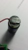
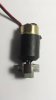
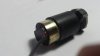
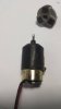
It looks like you have a 12 volt motor.
There is a switch that selects speed. 1,2,3,4,5,6,7,8,9,10,11, or 12mm/hour. (and maybe 0)
You want an Arduino to control the speed, not the switch.

It would be nice to know more about this "switch".

My guess is that this switch adds resistance to the motor to slow it down.
If you are using a micro-computer I would use a "PWM" function to reduce the voltage to the motor to slow it down.
Probably if you apply 12 volts (100% of the time) you get the 12mm/hr. If the computer were to apply 12V at 50% duty cycle then you will get a slower motor. I know someone that did this project recently. He got full speed at 12V and 1/4 speed at 50% and 1/16 at 25%. (approximately) You will need to make a lookup table.
0%=0mm/hr
10%=1mm/hr
......
......
90%=11mm/hr
98%=12mm/hr
 
The switch is probably the poor man's encoder. That could be replaced with a hall effect sensor.

I have a hard time envisioning 3mm/hr. Do you mean the tubing displacement? i.e 3 mm of tubing is squeezed in 1 hr. If it is, it's a displacement issue and that's what I THINK an infusion pump would need.

Motors run in RPM. mm of "what" per hour?

I envison there is some disc on the end of the motor that squeezes a tube and the displacement is 3mm along the circumference of that disc. Am I wrong?
 
The previous motor pics i uploaded are the motor pic from the old pump. thats how it looks. on this rotor there is 3 magnets attached as shown in the pics. then in the pump circuit there is a reed switch to reed or to off the circuit some how.
any ideas guys.
 
It would seem that it is a DC motor that uses the magnets and reed switch to move the measured distance by issuing a pulse until the switch is seen by the next magnet, you would need a processor to monitor the clock and issues to pulses as required.
My assumption is it operates on this step principle.
Max.
 
jembola747, Every one is just guessing what you are trying to achieve and what how the existing unit works. Trace out the wiring of the existing unit and post the shematic. Take some pictures of the mechanics of the unit. (Or describle in detail how it works.) Does the motor drive a threaded rod and the nut on the rod moves at the speeds that you quote in mm pet hour ? Does the motor drive the threaded rod directly or via a gearbox ? How much does the nut move on the threaded rod for one rotation of the motor ? (Or how many revolutions of the motor move it one mm ?)

Les.
 
guys i wan t to control the circuit like this . but still less secs, like 2seconds on and the whole hour off and continue until its finished. as the
**broken link removed**
 
The motor in the old pump have two wires only, and it drives very slowly when 9volts is given. Im not sure which type of motor it is.
 
I still asked how do you get the units of mm/hr unless it's along the circumference. Revolutions/min (RPM) or radians/sec are permissible.

So, if this is a peristaltic pump, displacement of the tubing would be measured in mm/time.

Running a brushed DC motor for a specific amount of time won;t always get you the same displacement. Speed depends on load and the motor could over-run. Dynamic braking can generally fix the over-run issue. A very simple way to do dynamic braking is to put a relay that shorts the motor when it's stopped.
 
It seems he is asking for x mm every 60 seconds. He's asking about a timer.

OP has no idea of what he actually needs or he is giving imprecise information.
 
The switch is probably the poor man's encoder. That could be replaced with a hall effect sensor.

I have a hard time envisioning 3mm/hr. Do you mean the tubing displacement? i.e 3 mm of tubing is squeezed in 1 hr. If it is, it's a displacement issue and that's what I THINK an infusion pump would need.

Motors run in RPM. mm of "what" per hour?

I envison there is some disc on the end of the motor that squeezes a tube and the displacement is 3mm along the circumference of that disc. Am I wrong?


there is a thread stainless steel rod at the end of the motor. it make rounds. the syringe is in millimeters, so the fluid is released when the motor runs.
 
Status
Not open for further replies.

Latest threads

New Articles From Microcontroller Tips

Back
Top