Continue to Site

Welcome to our site!

Electro Tech is an online community (with over 170,000 members) who enjoy talking about and building electronic circuits, projects and gadgets. To participate you need to register. Registration is free. Click here to register now.

  • Welcome to our site! Electro Tech is an online community (with over 170,000 members) who enjoy talking about and building electronic circuits, projects and gadgets. To participate you need to register. Registration is free. Click here to register now.

Programming 16F628 while connected to LCD

Status
Not open for further replies.

gregmcc

Member
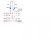
I've build a LCD clock using the schematic attached. The first time I program it using a Inchworm everything programs fine. If I recompile (mplab) and want to reprogram the PIC I keep getting errors. (verification failures)

I've done some fiddling and its to do with the PGM pin being connected to the LCD - if I disconnect the LCD it programs fine.

While this solution is ok I would like to program without disconnecting the pin all the time. I've tried a 10k resistor between the PIC pin10 and the LCD but no luck.

Whats the trick here to get it working?
 

Attachments

  • jp6285.gif
    jp6285.gif
    5.8 KB · Views: 1,867
Is your schematic complete? Add a 0.1uf cap across pins 5 & 14.

PGM can be disabled with a __CONFIG setting. _LVP_OFF also you may need to add _MCLR_OFF since you have no pullup on the MCLR pin.
 
Bill,

The schematic is not 100% (I got it and the.hex file from **broken link removed**) - I'm powering it from a stable 5V power supply and from the MCLR pin I have a diode and resistor to 5V (as in the inchworm hello world project)
 
Add the 0.1uf cap, it is important.
Also those 1 line LCDs can be tricky, here's an L/C meter with the same display and PIC16F84 (there is code for the 16F628 on the site too)
Jumper LK3 is for poorly behaved displays, the 10K pot is a much better solution than the 1K resistor.
**broken link removed**

**broken link removed**
 
I've added the cap and the 10k pot - made no difference. The problem is not with the LCD - once programmed everything works 100%. Its when I have to reprogram the PIC in circuit that I need to disconnect pin 10 on the PIC. I'm looking for a way to not have to disconnect the pin every time I want to reprogram it.
 
hi Greg

>> While this solution is ok I would like to program without disconnecting the pin all the time. I've tried a 10k resistor between the PIC pin10 and the LCD but no luck.

Whats the trick here to get it working?


The simplest way would be to install a 0.1inch pitch jumper, that would save desoldering.

I am not aware of any low cost component way of doing it.
 
Last edited:
If you turn off LVP in the config then there should be no way that the level on B4 should make any difference. Can you post the source file? Or even the hex file.

Mike.
Edit, you don't explain how you have your ICD2 connected. How are B6,7 connected? Have you tried a 10K resistor from the Enable line of the LCD to gnd?
 
Last edited:
Pommie - the LVP config bit is turned off. I've uploaded the source file.

The original .hex file can be found at **broken link removed**

Edit: I've just tried a 10k resistor on the enable pin - doesnt make any difference.

Here's a pic on my ICD2 wiring (its from Bill's hello world project)
 

Attachments

  • jp6285.asm
    25.7 KB · Views: 256
  • icd2.JPG
    icd2.JPG
    16 KB · Views: 413
Last edited:
When I am using B6,7 in the main circuit I have 1K resistors in the lines from ICD2 to pic. In this circuit I would also put a 10K resistor from the enable pin (RA1) on the LCD to Gnd, this ensures that the LCD cannot become active and interfere with B6,7.

Mike.
 
No such luck - I put the 10k to ground and the 1k resistors between the pic and icd2. I've even tried to short lcd enable to ground - it still refuses to be programmed while PGM is connected to the LCD.
 
The ICD2 (and Inchworm) both have 4.7K resistors to GND on the PGC & PGD pins. As long as the __CONFIG _LVP_OFF is there PGM should make zero difference.
A HVP programmer will ignore the LVP setting and pin and read/write in HVP mode.

PS how did you get MPLAB to assemble it? There are three very old commands that require modification before it will assemble. The assembler you're using might not set the fuses correctly in the hex file.

Did the "hello world" program work for you?

edit: ahh it's a disassembly of the hex file. Are you using a 16F628 or 16F628A?
 
Last edited:
I used mplab (latest version) and it assembled here fine.
The hello world project works 100% as well - I can reprogram it till I'm blue in the face and it works everytime.

What are the 3 old commands your mplab is complaining about?

Edit: Yip - its a dissasembly of the hex file. I'm going through the source to try and understand (and teach myself) exactly what is going on.

I'm using the 16F628
 
Greg,

You say it programs OK when you physically disconnect PIC pin #10 from the LCD???

As a test keep pin#10 connected as normal, start the program sequence and measure what voltage level is actually on pin #10 throughout the sequence, voltmeter or scope would do it.

Lets know what voltage level you see on this pin.
 
Without the comments and probably better labels it'll be tough going to decode someone elses source code, especially if you're not yet that familiar with the PIC. LCDs can be tricky until you get the hang of them, 4bit mode even more so.

The commands are (TRIS PORTx and OPTION)
they won't compile and have to be changed to movwf TRISx and movwf OPTION_REG
 
Eric - I've put a scope on pin 10 - its a constant 5V throughout the programming. I guess this is why it keeps failing. Dunno why I didnt think of doing this before! I've now put a 10k from pin 10 to ground and its working!!! Wooo hoo!! :)

Bill - I know its going to be tough, but I'm going through the code add tons of comments and proper labels - this way I can slowly step through the code finding out exactly what it does. I'm sure there's an easier way but I'll put it down to the learning process :)

Thanks for all the help!!
 
You might try using WinPicprog to disassemble it, as it adds labels for you - you still have to edit them to make sense, but at least it's one job less!.

Having said that, I've done it for you!.
 

Attachments

  • temp.zip
    2.8 KB · Views: 219
Last edited:
Status
Not open for further replies.

Latest threads

New Articles From Microcontroller Tips

Back
Top