Continue to Site

Welcome to our site!

Electro Tech is an online community (with over 170,000 members) who enjoy talking about and building electronic circuits, projects and gadgets. To participate you need to register. Registration is free. Click here to register now.

  • Welcome to our site! Electro Tech is an online community (with over 170,000 members) who enjoy talking about and building electronic circuits, projects and gadgets. To participate you need to register. Registration is free. Click here to register now.

Program done but pic does not execute it !!

Status
Not open for further replies.

BGAmodz

Member
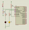
I have been reading a lot of tutorials the last days and i have managed to write a program for a dual blinking leds with switch .

I have completed the program using the C language , but when i load it on the PIC16F877A it does not apply it .

Here is a copy of the program :

int i ;
sbit sw at porta.b0 ;
sbit led_1 at porta.b1 ;
sbit led_2 at porta.b2 ;
void main () {
trisa.b0=1 ;
trisa.b1=0 ;
trisa.b2=0 ;

while(1) {
if(sw==1){
for(i=0;i<=5;++i){

led_1=1 ;
led_2=0 ;

delay_ms(1000) ;

led_1=0;
led_2=1;

delay_ms(1000);
}
}
else(led_1=0 )&&(led_2=0);
}
}

dTTeAnn.jpg
 
What configuration settings are you using at the beginning of the program? Show complete program please
 
In mikroc , am using 4Mhz , PIC16F877A when i first started new project , that all i was asked to configure .
That's the complete program straight from MikroC
 
In mikroc , am using 4Mhz , PIC16F877A when i first started new project , that all i was asked to configure .
That's the complete program straight from MikroC

Code:
int i ;
sbit sw at porta.b0 ;
sbit led_1 at porta.b1 ;
sbit led_2 at porta.b2 ;
void main () {
<---ADCON1 = 6;
trisa.b0=1 ;
trisa.b1=0 ;
trisa.b2=0 ;

while(1) {
if(sw==1){
for(i=0;i<=5;++i){

led_1=1 ;
led_2=0 ;

delay_ms(1000) ;

led_1=0;
led_2=1;

delay_ms(1000);
}
}
else(led_1=0 )&&(led_2=0);
}
}

Add in the line as indicated by the arrow and see if it works.
If it doesnt, put a 10K resistor from pin 1 of 16F877 (MCLR) to +5V and try again.

Allen
 
still nothing in both cases .

Actually in the tutorial I've read , here is how the program is done NOTICE THE LAST LINE , and it works , i don't know why it doesn't work on my compiler .
ORIGINAL TUTORIAL CODE :
int i ;
sbit sw at porta.b0 ;
sbit led_1 at porta.b1 ;
sbit led_2 at porta.b2 ;
void main () {
trisa.b0=1;
trisa.b1=0;
trisa.b2=0;
while(1) {
if(sw==1){
for(i=0;i<=5;++i){

led_1=1 ;
led_2=0 ;

delay_ms(1000) ;

led_1=0;
led_2=1;

delay_ms(1000);
}
}
else(led_1=0;led_2=0 ; )

}
}
 
OK, then put a 10K resistor between RA0 and ground. Your switch input is floating.

Allen
 
I don't know what the fxxxxxx is wrong , program is compiled and nothing works , her is what i get when i want to compile the original tutorial program !

Js7rkPV.jpg
 
The "else" statements are in the wrong brackets

else{led_1=0; led_2 = 0;} // curly brackets

C:
int i ;
sbit sw at porta.b0 ;
sbit led_1 at porta.b1 ;
sbit led_2 at porta.b2 ;
void main () 
    {
    trisa.b0=1;
    trisa.b1=0;
    trisa.b2=0;
    while(1) 
        {
        if(sw==1)
            {
            for(i=0;i<=5;++i)
                {

                led_1=1 ;
                led_2=0 ;

                delay_ms(1000) ;

                led_1=0;
                led_2=1;

                delay_ms(1000);
                }
            }
            else{led_1=0;led_2=0 ; } // <--- curly brackets

        }
    }
 
Even when i apply 5 volts to the MCLR/ , nothing happens , the program is running fine but the PIC on ISIS does not run it
 
are you using the internal oscillator or external??
if external than you have to connect it to the hardware in ISIS
 
are you using the internal oscillator or external??
if external than you have to connect it to the hardware in ISIS
No you don't..... It isn't simulated... You don't need to put it in...
 
here is another program , this one works but not as supposed to be working , i need to press 3 times the button to light up the led , but whe i simulate it , the led lights up before i press the button .

int x ;
int flag ;
sbit sw at portb.b1 ;
sbit led at portb.b0 ;
void main () {
trisb.b0=0;
trisb.b1=1;
flag=0;
while(1){
if(sw==1&&flag==0){
flag=1 ;
x=x+1 ;
}
if(sw==0){
flag=0;
}
if(x==3){
x=0;
led=1;
delay_ms(500);
led=0;
}
}
}
 
I converted your program to HiTech C and it works on the ISIS..

The converted program as attached

Code:
#include <htc.h>
#define _XTAL_FREQ 4000000

int i ;
#define sw RA0
#define led_1 RA1
#define led_2 RA2

void main () {
ADCON1 = 6;                //make port A digital
TRISA = 0b00000001 ;    //ra0 input, ra 1&2 output

while(1) {
if (sw == 1) {
for(i=0;i<=5;++i){

led_1=1 ;
led_2=0 ;

__delay_ms(1000) ;        //one second delay

led_1=0;
led_2=1;

__delay_ms(1000);
}
}
else { led_1=0; led_2=0; }
}
}

I also attached the isis sim and the hex file. You may try my hex file and see if it works on your ISIS and hardware circuit.

Allen
 

Attachments

  • blink 877A.PNG
    blink 877A.PNG
    33.2 KB · Views: 211
  • blink 877A.hex
    603 bytes · Views: 141
Last edited:
Yuo say "code is good".

The fact that the compiler does compile it means that your wrote it the right way. It does not say that is hardware-wise correct.

You were asked if you could single-step it.

Simulation is in order to see if you are doing what is actually needed to get what you expect.
 
Status
Not open for further replies.

Latest threads

New Articles From Microcontroller Tips

Back
Top